Diese Version enthält möglicherweise inkorrekte Änderungen. Wechsle zur letzten geprüften Version.
Was du brauchst
-
Dieser Schritt ist noch nicht übersetzt. Hilf mit, ihn zu übersetzen!
-
Start by using a spudger or plastic opening tool to remove the bottom cover.
-
Once enough of the glue is removed, peel the cover off by hand,
-
-
Dieser Schritt ist noch nicht übersetzt. Hilf mit, ihn zu übersetzen!
-
Remove the four 7.5mm length Philips head screws under the rubber cover.
-
-
Dieser Schritt ist noch nicht übersetzt. Hilf mit, ihn zu übersetzen!
-
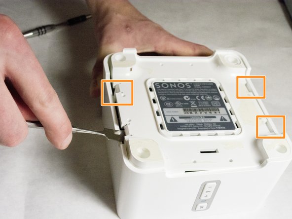
Use a nylon spudger to unsnap the bottom from the sides.
-
Pry until the remaining three points are unsnapped.
-
Once unsnapped, lift the cover.
-
-
Dieser Schritt ist noch nicht übersetzt. Hilf mit, ihn zu übersetzen!
-
Remove the connection for the front buttons to fully remove the cover.
-
-
-
Dieser Schritt ist noch nicht übersetzt. Hilf mit, ihn zu übersetzen!
-
Use a plastic opening tool or spudger to remove the adhesive covering the the WIFI connectors.
-
Gently pull the wires at the connection point to disconnect them from the motherboard.
-
-
Dieser Schritt ist noch nicht übersetzt. Hilf mit, ihn zu übersetzen!
-
Remove the two pieces of glue holding the WIFI card in place.
-
-
Dieser Schritt ist noch nicht übersetzt. Hilf mit, ihn zu übersetzen!
-
Scrape the glued pad underneath the WIFI card to seperate the card from the board.
-
Push apart the two clips holding the WIFI card in the connection.
-
Pull the WIFI card out of the connection.
-
-
Dieser Schritt ist noch nicht übersetzt. Hilf mit, ihn zu übersetzen!
-
Remove the 7mm length Phillips screw holding the board in place.
-
-
Dieser Schritt ist noch nicht übersetzt. Hilf mit, ihn zu übersetzen!
-
Flip the board over to access the Molex Cable.
-
-
Dieser Schritt ist noch nicht übersetzt. Hilf mit, ihn zu übersetzen!
-
Disconnect the Molex Cable from the top motherboard.
-


Rückgängig: Ich habe diese Anleitung nicht absolviert.
2 weitere Nutzer:innen haben diese Anleitung absolviert.
Team

IUPUI, Team 3-2, Baechle Spring 2016 Mitglied von IUPUI, Team 3-2, Baechle Spring 2016
IUPUI-BAECHLE-S16S3G2
4 Mitglieder
4 Anleitungen geschrieben