Einleitung
The motherboard is the circuit that connects all of the parts within the tablet. It is essential to the proper function of the device. Damage to the motherboard often prevents the device from turning on or performing tasks correctly and usually requires that the motherboard be replaced. The most common cause of damage is exposure to water.
The disassembly is slightly more involved than the other replacement guides for this device. The use of a soldering iron is required to disconnect all of the wires connecting to the motherboard. Be sure to review the iFixit soldering guide if you do not have experience using a solder iron. You will also need to remove a couple of screws in order to take out the motherboard.
Was du brauchst
-
-
Use a plastic opening tool to gently pry the back panel assembly apart from the front casing.
-
Start on one edge of the device by inserting the plastic opening tool between the back panel and the front casing using a gentle rocking motion.
-
-
-
Once you have successfully separated one edge of the back panel from the front casing, slide the plastic opening tool along the other edges to detach them as well.
-
-
-
-
The plastic volume button cover may fall out when you remove the back panel. Set it aside.
-
-
-
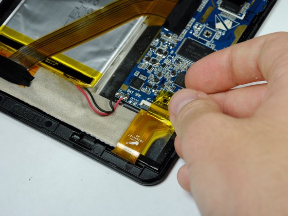
Remove the 4 pieces of tape covering the zero insertion force (ZIF) connectors on the motherboard.
-
-
-
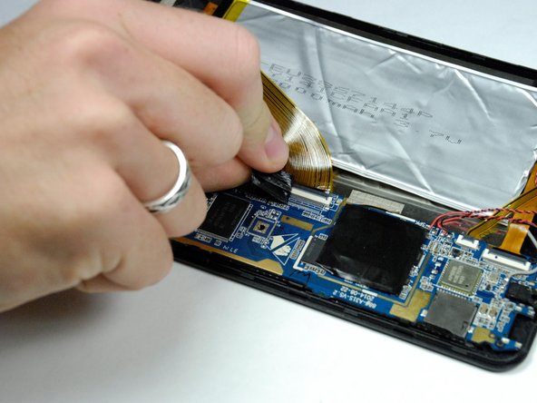
Use a spudger to flip up the black flaps on each of the 4 ZIF connectors.
-
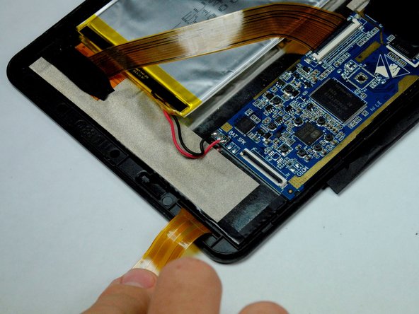
Once the flaps are up, use your fingers to disconnect the end of the ribbon wires from the connectors.
-
-
-
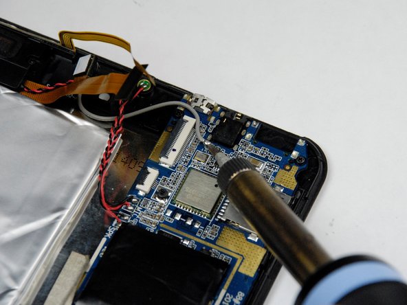
Use the soldering iron to melt away the solder from each of the wires connecting to the motherboard.
-
Once the solder is completely removed, pull the wires away from the motherboard.
-
-
-
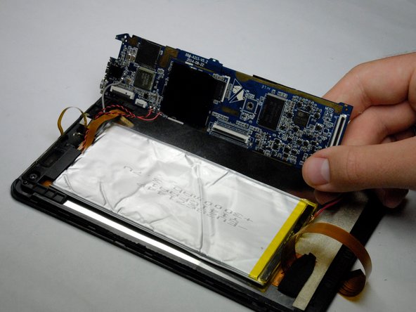
Use a J00 Phillips head screwdriver to remove the two 4.3 mm screws securing the motherboard to the device and set them aside.
-


To reassemble your device, follow these instructions in reverse order.
To reassemble your device, follow these instructions in reverse order.
Rückgängig: Ich habe diese Anleitung nicht absolviert.
Ein:e weitere:r Nutzer:in hat diese Anleitung absolviert.
Team

Baylor, Team 4-1, Williams Fall 2015 Mitglied von Baylor, Team 4-1, Williams Fall 2015
BU-WILLIAMS-F15S4G1
4 Mitglieder
10 Anleitungen geschrieben