Diese Version enthält möglicherweise inkorrekte Änderungen. Wechsle zur letzten geprüften Version.
Was du brauchst
-
Dieser Schritt ist noch nicht übersetzt. Hilf mit, ihn zu übersetzen!
-
Unplug any cables from the USB, power, display or DVI-D ports by gripping the cord by the connector and pulling straight out of the port.
-
-
Dieser Schritt ist noch nicht übersetzt. Hilf mit, ihn zu übersetzen!
-
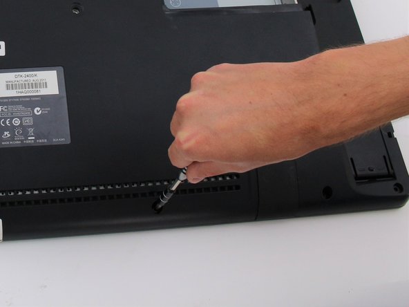
Place the device screen down on a flat surface.
-
Remove eight 10mm Phillips #2 screws (four on each leg of the stand) by turning the screwdriver counterclockwise.
-
-
Dieser Schritt ist noch nicht übersetzt. Hilf mit, ihn zu übersetzen!
-
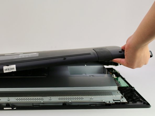
Lift the stand up and away from the rest of the device so the legs separate from the mounting plate.
-
-
-
Dieser Schritt ist noch nicht übersetzt. Hilf mit, ihn zu übersetzen!
-
Remove eighteen 10.2mm Phillips #1 screws from the perimeter of the back panel by turning the screwdriver counterclockwise.
-
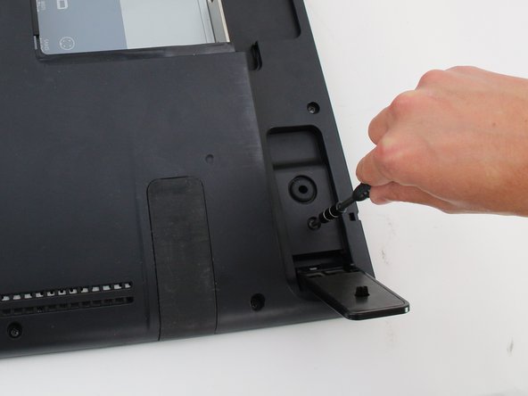
Remove one 11.9mm Phillips #1 screw from the center of the back panel.
-
Remove two 10.2mm Phillips #1 screws from underneath hinged panels in the bottom right and left corners.
-
-
Dieser Schritt ist noch nicht übersetzt. Hilf mit, ihn zu übersetzen!
-
Lift the back panel up by a corner and insert a plastic opening tool in the gap.
-
Slide the tool along the gap around the perimeter of the device while lifting to unlatch the back panel.
-
Remove the panel by lifting it up and off of the device.
-
-
Dieser Schritt ist noch nicht übersetzt. Hilf mit, ihn zu übersetzen!
-
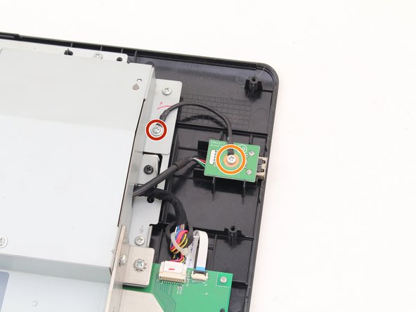
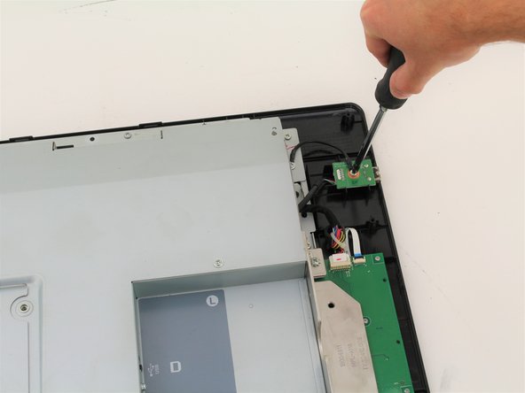
Remove one 8mm Phillips #2 screw by turning the screwdriver counterclockwise
-
Remove one 9.9mm Phillips #2 screw by turning the screwdriver counterclockwise.
-
-
Dieser Schritt ist noch nicht übersetzt. Hilf mit, ihn zu übersetzen!
-
Remove the black grounding wire by lifting up.
-
Remove the USB port board by pinching the wiring close to the connector and gently pulling out.
-
-
Dieser Schritt ist noch nicht übersetzt. Hilf mit, ihn zu übersetzen!
-
Remove the USB port by melting the soldered connections with a soldering iron, then pulling the port off of the board.
-


Rückgängig: Ich habe diese Anleitung nicht absolviert.
Ein:e weitere:r Nutzer:in hat diese Anleitung absolviert.
Team

Cal Poly, Team S15-G3, White Fall 2018 Mitglied von Cal Poly, Team S15-G3, White Fall 2018
CPSU-WHITE-F18S15G3
4 Mitglieder
18 Anleitungen geschrieben