Einleitung
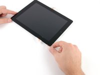
Use this guide to replace the volume and power button cable assembly in your iPad 2 GSM. This assembly also includes the sensor responsible for detecting the magnet in a Smart Cover.
Parts of this guide were shot with a Wi-Fi model and as such the internals may look slightly different from the cellular model. The procedure is the same for both models except where noted.
Was du brauchst
-
-
Heat the iOpener for thirty seconds.
-
Throughout the repair procedure, as the iOpener cools, reheat it in the microwave for an additional thirty seconds at a time.
-
-
-
Remove the iOpener from the microwave, holding it by one of the two flat ends to avoid the hot center.
-
-
-
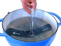
Fill a pot or pan with enough water to fully submerge an iOpener.
-
Heat the water to a boil. Turn off the heat.
-
Place an iOpener into the hot water for 2-3 minutes. Make sure the iOpener is fully submerged in the water.
-
Use tongs to extract the heated iOpener from the hot water.
-
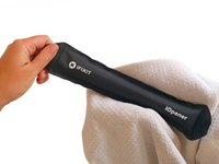
Thoroughly dry the iOpener with a towel.
-
Your iOpener is ready for use! If you need to reheat the iOpener, heat the water to a boil, turn off the heat, and place the iOpener in the water for 2-3 minutes.
-
-
-
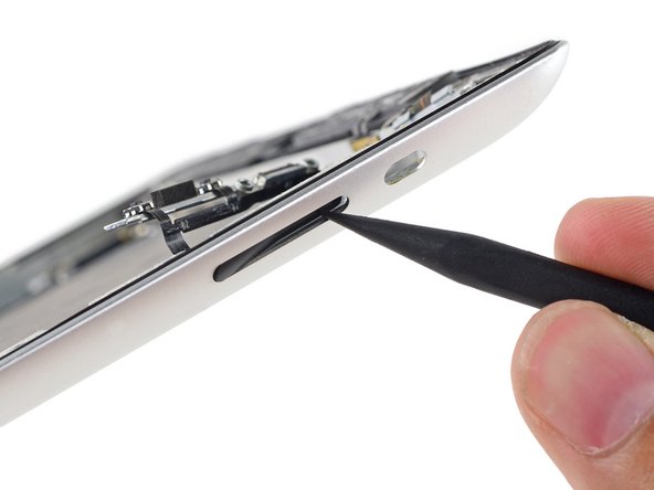
If your display glass is cracked, keep further breakage contained and prevent bodily harm during your repair by taping the glass.
-
Lay overlapping strips of clear packing tape over the iPad's display until the whole face is covered.
-
Do your best to follow the rest of the guide as described. However, once the glass is broken, it will likely continue to crack as you work, and you may need to use a metal prying tool to scoop the glass out.
-
-
In diesem Schritt verwendetes Werkzeug:Safety Glasses$3.19
-
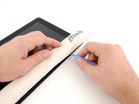
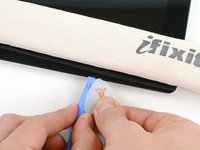
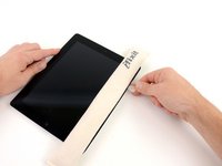
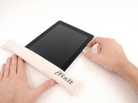
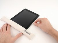
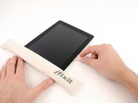
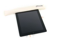
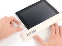
Lay the iOpener flat on the right edge of the iPad, smoothing it out so that there is good contact between the surface of the iPad and the iOpener.
-
Let the bag sit on the iPad for approximately 90 seconds before attempting to open the front panel.
-
-
-
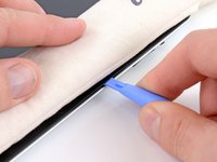
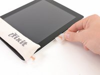
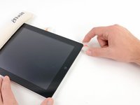
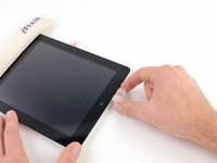
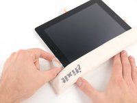
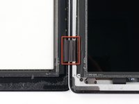
There is a small gap in the iPad's adhesive ring in the upper right corner of the iPad, approximately 2.0 inches (~5 cm) from the top of the iPad. You are going to exploit this weakness.
-
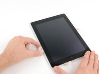
Align the tool with the mute button. Insert the tip of a plastic opening tool into the gap between the front glass and the plastic bezel. Just insert the very tip of the opening tool, just enough to widen the crack.
-
-
-
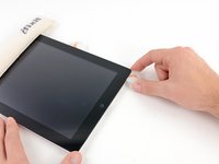
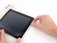
Make sure you place the tool in the proper spot—between the plastic display bezel and the front panel glass.
-
-
-
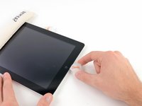
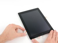
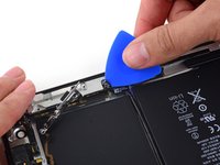
Keeping the tip of the plastic opening tool wedged between the front glass and plastic bezel, slide a plastic opening pick in the gap, right next to the plastic opening tool.
-
-
-
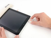
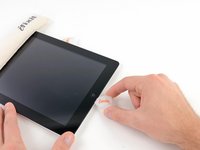
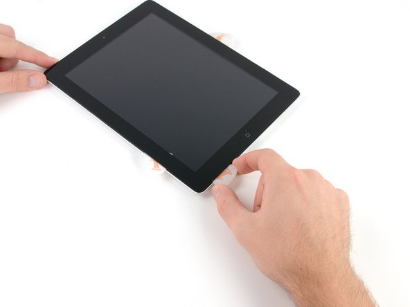
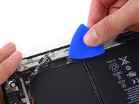
Remove the plastic opening tool from the iPad, and push the opening pick further underneath the front glass to a depth of ~0.5 inches.
-
-
-
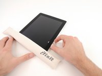
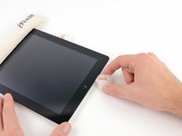
While you work on releasing the adhesive on the right side of the iPad, reheat the iOpener, and replace it on the bottom edge of the iPad.
-
-
-
While the bottom edge is being heated by the iOpener, begin releasing the adhesive from the right edge of the iPad.
-
Slide the opening pick down along the edge of the iPad, releasing the adhesive as you go.
-
-
-
If the opening pick gets stuck in the adhesive, "roll" the pick along the side of the iPad, continuing to release the adhesive.
-
-
-
Before removing the first opening pick from the bottom corner of the iPad, insert a second pick under the right edge of the front glass to keep the adhesive from re-adhering.
-
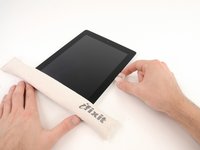
Re-heat the iOpener, and move it to the top edge of the iPad.
-
-
-
You will have to release the adhesive securing the antenna to the front panel without damaging the delicate parts attaching the antenna to the bottom of the iPad. Follow the next steps carefully.
-
-
-
Slide the opening pick around the bottom right corner of the iPad, releasing the adhesive there.
-
-
-
Slide the tip of the opening pick along the bottom edge of the iPad, releasing the adhesive over the Wi-Fi antenna.
-
-
-
Once you have moved past the Wi-FI antenna (approximately 3" (75 mm) from the right edge, or right next to the home button) re-insert the opening pick to its full depth.
-
Slide the pick to the right, releasing the adhesive securing the Wi-Fi antenna to the front glass.
-
The antenna is attached to the bottom of the iPad via screws and a cable. This step detaches the antenna from the front panel, ensuring that when you remove the panel, the antenna will not be damaged.
-
-
-
Continue releasing the adhesive along the bottom of the iPad, pulling the opening pick out far enough to go around the home button, and re-inserting it to a depth of 1/2 inch (10 mm) once the pick is past the home button.
-
-
-
-
Continue releasing the adhesive all the way along the bottom edge of the iPad.
-
Leave the opening pick wedged underneath the front glass near the home button.
-
-
-
Reheat the iOpener in the microwave and set it on the left edge of the iPad to start warming the adhesive in that section.
-
-
-
Slide the opening pick along the top edge of the iPad, pulling it out slightly to go around the front-facing camera bracket.
-
The adhesive along this section is very thick, and a fair amount of force may be required. Work carefully and slowly, making sure to not slip and damage yourself or your iPad.
-
-
-
Continue releasing the adhesive along the top edge of the iPad, and slide the opening pick around the top left corner.
-
-
-
Slide the opening pick along the left edge of the iPad, releasing the adhesive as you go. The adhesive is thin here due to the digitizer along the whole left side. Make sure the pick is not too deep (max 1/2 inch) 10 mm to prevent damaging the digitizer.
-
-
-
Using the opening pick that is still underneath the bottom edge of the iPad, release the adhesive along the bottom left corner.
-
-
-
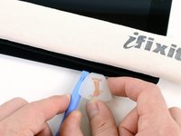
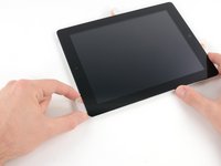
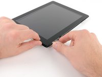
Using one of the opening picks, pry up the bottom right corner of the iPad and grab it with your fingers.
-
-
In diesem Schritt verwendetes Werkzeug:Microfiber Cleaning Cloths$3.99
-
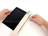
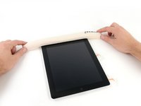
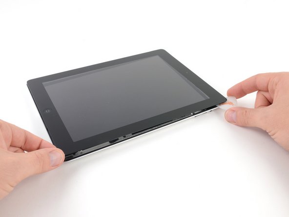
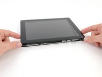
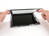
Holding the iPad by the top and bottom right corners, rotate the front glass away from the iPad.
-
-
-
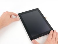
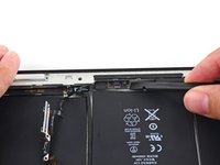
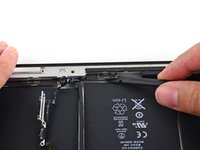
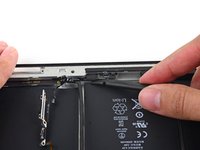
Lift the LCD from its long edge closest to the volume buttons and rotate it out of the rear case.
-
Lay the LCD on the front panel as seen in the second picture.
-
-
-
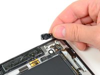
Carefully peel the rubber cover off the metal camera retainer and remove it from the iPad 2.
-
-
-
Remove the following two screws:
-
One 3.3 mm Phillips screw
-
One 2.1 mm Phillips screw
-
Lift the metal retainer clip straight up from its recess in the rear panel.
-
-
-
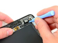
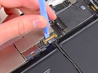
Use a plastic opening tool to pry the rear camera connector up from its socket on the upper component board.
-
Remove the rear camera.
-
-
-
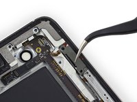
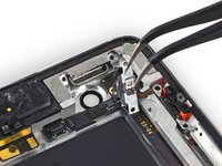
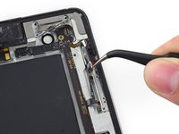
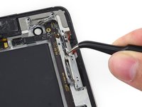
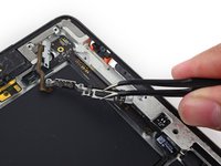
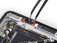
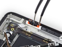
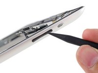
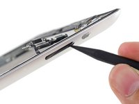
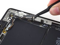
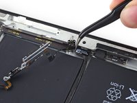
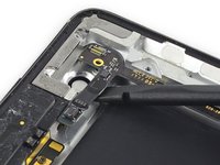
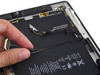
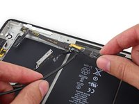
Use the tip of a spudger to flip the retaining tab on the ZIF connector to release the GPS cable.
-
-
-
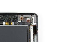
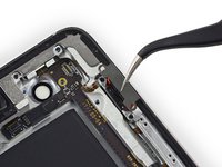
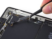
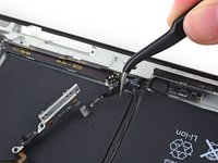
Remove the following screws from the volume/power button assembly cable:
-
Two 2.5 mm Phillips #000 screws, at a 45º angle securing the power button.
-
Two 5 mm Phillips #000 screws
-
One 2 mm Phillips #000 screw at a 45º angle.
-
-
-
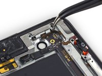
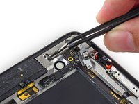
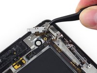
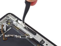
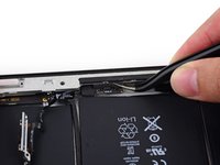
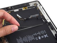
Pull the power button cable out of the recess in the rear case and bend it out of the way.
-
-
-
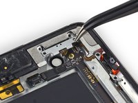
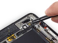
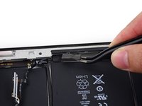
Use the center screw hole of the volume control bracket to tilt it out toward the edge of the case and then pull it up out of its recess.
-
-
-
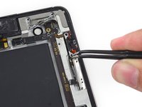
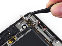
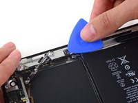
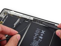
Gently peel the power and volume button cable away from the rear case.
-
Bend the cable toward the inside of the rear case, but do not attempt to remove it as it is still connected to the upper component board.
-
-
-
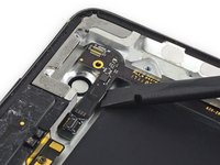
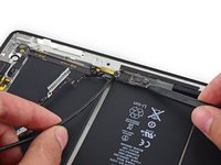
Use the tip of a spudger to push the volume rocker into the interior of the rear case.
-
Remove the volume rocker from the rear case.
-
-
-
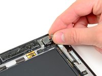
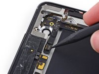
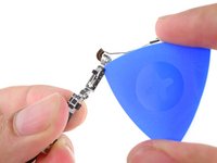
Use the point of an opening pick to gently peel the Smart Cover sleep/wake sensor up off the rear case.
-
-
-
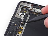
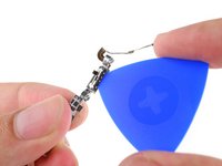
Carefully peel the volume rocker portion of the button cable away from the rear case.
-
-
-
Remove the single 2 mm Phillips #000 screw from the lower end of the upper component board.
-
-
In diesem Schritt verwendetes Werkzeug:Tweezers$4.99
-
Use a set of tweezers to remove the foam block from between the rear case and the upper component board.
-
-
-
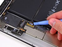
Insert a spudger under the end of the upper component board and gently slide it toward the volume rocker to free the board from adhesive.
-
-
-
Insert a spudger under the GPS connector end of the upper component board and lift it up off of its adhesive.
-
-
-
Flip up the retaining bar securing the upper component board cable connector.
-
Pull the connector straight out of its socket on the logic board.
-
-
-
Lift the end of the upper component board cable up off of the adhesive holding it to the rear case.
-
-
-
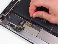
Insert the tip of a spudger under the upper component board to lift it slightly.
-
Pull the board up and out of the space between the battery and the rear case bezel.
-
Remove the upper component board.
-
-
-
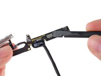
Peel the tape covering the button cable connector off of the upper component board.
-
-
-
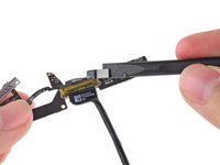
Lift the button cable connector straight up off of its connector on the upper component board.
-
-
-
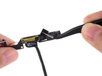
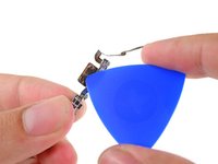
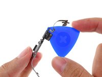
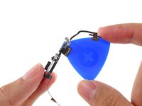
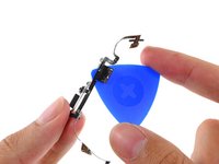
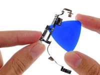
Insert the point of an opening pick between the rotation lock/silent switch and its bracket to sever the adhesive there.
-
-
-
Slide the opening pick under the remaining portion of the rotation lock/silent switch to peel it up off the button bracket.
-
-
-
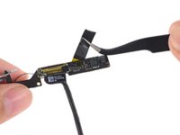
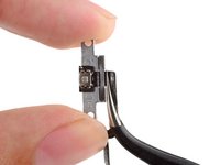
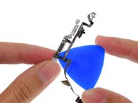
Use the point of the opening pick to peel the mechanical volume buttons up from the bracket.
-
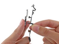
Remove the button cable assembly from the button bracket.
-


To reassemble your device, follow these instructions in reverse order.
To reassemble your device, follow these instructions in reverse order.
Rückgängig: Ich habe diese Anleitung nicht absolviert.
50 weitere Personen haben diese Anleitung absolviert.


5 Kommentare
Great guide!!!! It was hard but great details!!!
i replaced this cable and now the screen went to dim to no pic please help
I would rather gouge my eyes out with a wooden spoon than ever have to do this repair again! It was the hardest repair I have ever done!! I will never rip another power button flex cable again