Diese Übersetzung enthält möglicherweise noch nicht die neuesten Änderungen der Original-Anleitung. Hilf mit, die Übersetzung zu aktualisieren oder sieh dir die Original-Anleitung an.
Einleitung
Benutze diese Anleitung, um das Logic Board deines iPhones zu ersetzen.
Was du brauchst
-
-
Schalte dein iPhone aus, bevor du es auseinanderbaust.
-
Deine iPhone Rückabdeckung ist entweder mit zwei Kreuzschlitzschrauben #000 oder Pentalobeschrauben von Apple befestigt. Schaue nach, um welche Schrauben es sich handelt, um sicher zu gehen, dass du den richtigen Schraubendreher zum Lösen hast.
-
Entferne die beiden 3,6 mm Pentalobe oder Kreuzschlitzschrauben #000 neben dem Dock Anschluss.
-
-
-
Schiebe die Rückabdeckung in Richtung Oberkante des iPhones.
-
-
-
Entferne das hintere Panel von Hand vom iPhone. Verwende alternativ einen Saugheber.
-
-
-
Entferne die einzelne 1,5 mm Kreuzschlitzschraube, die den Akkustecker am Logic Board befestigt (falls vorhanden).
you do not need to take the battery out as chuck said so you dont run the risk of braking the battery connector socket from the logic board
Won't you need the battery removed to access the large-headed screws on the side which hold the front display?
Unfortunately the battery screw was already stripped probably from original assembly. We used a pair of nail clippers as pliers to grab a hold of the screw by the edges to turn it. If it hadn't have been for the stripped screw it would have taken us about 10 minutes, as it was it took us 30-40 minutes if you count searching for solutions for removing the stripped screw.
-
-
-
Benutze die Kante eines Plastiköffnungswerkzeugs um den Akkustecker vorsichtig aus seinem Anschluss auf dem Logic Board nach oben zu hebeln.
-
Entferne die Metallklammer, die den Antennenstecker bedeckt.
-
-
-
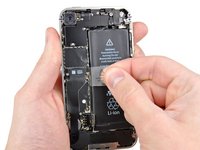
Ziehe die freiliegende durchsichtige Plastiklasche nach oben, um den Akku von dem Klebeband zu lösen, mit dem er am iPhone befestigt ist.
-
Wenn noch Reste vom Alkohol im Smartphone verblieben sind, dann wische sie sorgfältig weg oder lasse das Gerät gut austrz, bevor du einen neuen Akku einbaust.
-
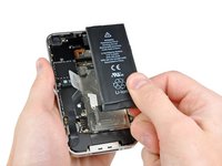
Entferne den Akku.
-
Reinige vor dem Wiederzusammenbau alle metallenen Kontaktpunkte mit einem fettlösenden Reiniger wie Windex. Die Öle an deinen Fingern können drahtlose Interferenzen verursachen.
-
Führe nach dem Wiederzusammenbau einen Hard Reset durch. Dies verhindert diverse Probleme und vereinfacht eine eventuell trotzdem notwendige Fehlersuche.
Note that the pull tab is not actually attached to the battery. It is attached to the iPhone chassis, and is only used to separate the battery from the adhesive. (Don't expect it to come out with the battery!)
Also, the adhesive is VERY strong. I had to use my plastic opening tool to assist in prying the battery loose. This is probably the most nerve-wracking part of the job.
It is much easier to slightly WARM the battery with a HAIRDRYER not a HEAT GUN to soften the adhesive. DO NOT GET BATTERY HOT AND DO NOT USE HEAT GUN
Joe -
I just did this today. Everything was as scripted. Mine had lots of adhesive and had to use plastic spudger to go around battery to loosen up. Do not use plastic tab until you can see under battery a little bit. Great instructions. Took less than 10 minutes.
The adhesive is very strong and I was initially worried about damaging the phone by prying so much. There are a couple of places below the volume switch where you can pry between the metal of the case and the battery. If you lift the battery just a little, wiggle the pry bar further in and then start moving down the case. Don't worry about bending the battery, its dead anyway.
Do not pry on the left side (circuit board side) and do not use the pull tab until the adhesive is broken loose.
I tried this at first with a plastic pry tool, and the adhesive was so strong that I broke the tool. I then used a large screwdriver and applied pressure very slowly along various places on the outer side of the battery. That eventually did the trick.
-
-
-
Entferne die beiden 1,8 mm Kreuzschlitzschrauben, die das Dockanschluss-Kabel am Logic Board befestigen.
-
Entferne die dünne Metall-Kabelabdeckung des Dockanschlusses.
-
-
-
Benutze die Kante eines Plastiköffnungswerkzeugs, um das Dock-Kabel aus seinem Sockel auf dem Logic Board hochzuhebeln.
-
-
-
-
Löse das Dockanschluss-Kabel vom Kleber ab, mit dem es am Logic Board und an der Seite des Lautsprechergehäuses befestigt ist.
-
-
-
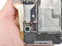
Entferne die 1,6 mm Kreuzschlitzschraube, mit der der Druckkontakt am Logic Board neben dem Vibrationsmotor befestigt ist.
-
Entferne des Druckkontakt.
-
-
-
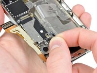
Benutze die Kante eines Plastiköffnungswerkzeugs, um das Kabel der Mobilfunkantenne aus seinem Anschluss auf dem Logic Board zu hebeln.
-
Löse das Kabel der Mobilfunkantenne unter den Metallstiften, die am Logic Board befestigt sind, heraus.
-
-
-
Entferne folgende fünf Schrauben:
-
Drei 1,3 mm Kreuzschlitzschrauben
-
Eine 1,5 mm Kreuzschlitzschraube
-
Eine 2,4 mm Kreuzschlitzschraube
Careful here...On my phone, the little mounting screw boss (the part the screw threads into) of the top red-circled screw came unglued/welded from the underlying board, meaning the screw will no longer be able to be screwed back in.
The three 1.3 mm screws are very difficult to distinguish from the 1.5 mm screw. I spent a long time with a magnifying glass trying to tell them apart. For the other steps of the repair, I kept the screws in a tray compartment along with the piece that they connected, but for this step I recommend keeping each of the different types of screws separate.
-
-
-
Hebe die Kabelabdeckung an der Kante oben am iPhones an.
-
Ziehe die Rasten der Kabelabdeckung aus ihren Schlitzen in der EMI Abdeckung auf dem Logic Board und entferne sie vom iPhone.
-
-
-
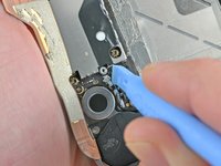
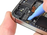
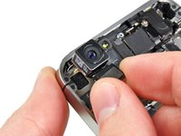
Benutze die Kante eines Plastiköffnungswerkzeugs, um den Stecker der Rückkamera aus seinem Anschluss auf dem Logic Board zu hebeln.
-
Entferne die Rückkamera vom iPhone.
Better to delay removing the camera and its cable until the Display and Digitizer cables are removed as there is an arm on the right side of the camera that slips under the other cables.
I agree with ed -- move the camera removal step until after Step 16, after the digitizer and display cables have been removed, as there is a tab/arm on the camera's cable that should go under these two cables during reassembly.
-
-
-
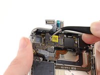
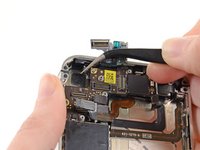
Trenne die fünf Kabel nahe der Oberkante des Logic Boards in der folgenden Reihenfolge:
-
Kabel der Kopfhörerbuchse/des Lautstärkereglers
-
Kabel der Ein-/Ausschalttaste
-
Frontkamera-Kabel
-
Touchscreen-Kabel
-
Displaydatenkabel
-
Benutze die Kante eines Plastiköffnungswerkzeugs, um die Kabel zu trennen. Heble damit vorsichtig ihre Stecker hoch und aus ihren Anschlüssen auf dem Logic Board heraus.
The Digitizer Cable on the new display seems to be too short. Trying to make it reach. It doesn't reach its place on the logic board. Going to disassemble and start over. (Step 15)
Any pointers?
What happened was there is a tab on the cable, and that didn't go all the way through the casing. I made this mistake about 3 times. It's not too short, just move the screen a little away from the casing, and pull the cable all the way through without ripping it.
⚠️ On reassembly, before plugging in the screen/digitizer cables, put the rear facing camera back in. There's a prong on the camera that lays underneath them.
-
-
-
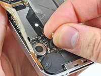
Entferne die 1,5 mm Kreuzschlitzschraube #000 bei der Kopfhörerbuchse.
take out screw on top of stand of first, then take of grounding plat, and then stand off.
This is correct.
Echoing the notes from 'boo' and Corey -- that's exactly what I saw too. Perhaps the guide should be updated?
This has been changed several times on the iphone 4 logic board manual, and the changes are always being reverted. There _IS_ a screw in step 16, but someone seems intent on not having it mentioned in the manual. Dunno why...
Because it's mentioned in Step 20.
It may have been mentioned in step 20 at some point, but it isn't anymore. The phillips head screw that's mentioned in step 20 is the one holding the grounding finger to the rear-facing camera corner of the motherboard.
That said, my concerns about step 16 have since been rectified, so I suppose step 20 could've been fixed at the same time.
There's a little rubber piece that you can see in the Step 17 & Step 21 pictures just above the yellow sticker. It fits over the edge of the board where the two ribbon cables from the display/digitizer come up through the board (Step 36). It's there to make sure the ribbon cables don't rub against the sharp edge of the board. This piece loves to fall out when pulling the logic board off. Make sure to put it back in when routing the cables in Step 36, thin edge on the bottom, thicker edge on the top.
-
-
-
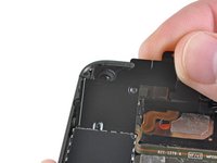
Hebe die kleine Erdungsklammer vom Logic Board ab und entferne sie vom iPhone.
Can you show how this piece attaches?
-
-
-
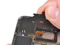
Benutze die Kante eines Plastiköffnungswerkzeugs, um den Stecker des Wi-Fi Antennenkabels vom Logic Board zu lösen.
For me, aligning the connector when putting things back together was the most difficult part of this repair. Unlike reattachment of the radio antenna in step 11, it is very difficult to see whether the male/female are aligned properly before applying pressure. Unfortunately, I have no secret as to how to accomplish this, other than to say that my WiFi is working after the repair.
-
-
-
Entferne die 2,5 mm Kreuzschlitzschraube #000, die das Logic Board bei der Ein-/Ausschalttaste befestigt.
-
Entferne die 4,8 mm Abstandsschraube bei der Kopfhörerbuchse.
I’d use a Phillips 00 instead of a flathead
-
-
-
Entferne die 3,4 mm Kreuzschlitzschraube beim Vibrationsmotor.
-
Entferne die beiden 3,6 mm Abstandsschrauben entlang der Seite des Logic Boards bei der Vertiefung für den Akkus.
When replacing the standoff screw closest to the dock connector, make sure it is tightened all the way down. The battery terminal screw fits in the standoff later, and if the standoff isn't tight (NOT TOO TIGHT!) then the battery will not be completely connected and your phone will power off unless tethered. This mimics a bad logic board symptom! Inspect this before replacing your logic board!
-
-
-
Hebe das Logic Board vorsichtig an der Kante beim Lautsprechergehäuse an und schiebe es von der Oberkante des iPhones weg.
-
Entferne das Logic Board.
When I was attempting to reinstall the logic board (step 21 in reverse), a small rubber bumper came loose from 'somewhere' on the board (I think). It isn't visible in any of the photos, so I really have no idea where it came from!
I don't see it in the pictures either, but I'm pretty sure there is a black bumper that rides on the 'top' of the logic board. I believe it reduces friction between the display/digitizer cables and the top of the logic board.
You can see this "bumper" in steps 16 and 20 (right above the yellow sticker in the pics), and it provides relief for the digitizer and display cables as they both come up and around the edge of the logic board. I put my bumper with its thicker side down towards the inside of the phone and it worked fine.
The rubber bumper has a groove in it, which rides a notch along the top edge of the logic board. Its purpose is to ease pressure between the top of the phone and the board. If you look at the top of the frame, there is a little horizontal ridge about 0.8cm (3/8") long which is just the right width of the rubber bumper.
For reference:
Your images show incorrect placement of the rubber spacer. Step 20 shows correct placement. It is just above the scan code sticker on the motherboard. That is where the ribbon cables roll over, so it makes sense.
I assume the thick side would be facing the rear of the phone, but can not be sure.?
I wouldn't use Windex. It's mostly water. Why would anyone put water on a connection? Use isopropyl alcohol and be certain that it's at least 95% alcohol.
Better yet use contact cleaner or the original Brakleen (in the RED can). You can find the Brakleen at any automotive store.
I experienced that when the rubber spacer had the thick side up towards the rear of the phone, the display data cable would plug in but had enough pressure from the rubber bumper pushing up that it would eventually become partially unplugged. This may not be immediately apparent while putting the phone back together because of still being partially plugged in. This was not an issue when the thin side was installed facing up towards the back of the phone.
-
-
Hope someone can ease my uncertainty: does the grounding finger for the
rear-facing camera go on TOP of the motherboard OR between the motherboard and
the standoff???
Under. There is nothing to ground if it went over the pcb. Look on the backside.


Um dein Gerät wieder zusammenzubauen, folge dieser Anleitung in umgekehrter Reihenfolge.
Um dein Gerät wieder zusammenzubauen, folge dieser Anleitung in umgekehrter Reihenfolge.
Rückgängig: Ich habe diese Anleitung nicht absolviert.
42 weitere Personen haben diese Anleitung absolviert.
Besonderer Dank geht an diese Übersetzer:innen:
92%

Annika Faelker hilft uns, die Welt in Ordnung zu bringen! Wie kann ich mithelfen?
Hier starten ›

Pra descarregar a bateria, antes de fazer o serviço, isso serve pra qualquer celular?
Gilmar Dutra - Antwort