Zum Hauptinhalt wechseln

A1706 / EMC 3071 - herausgekommen im November 2016. Dieses 13" Macbook Pro führt die OLED Touch Bar ein. Es bietet einen Dual-Core "Skylake" Intel Core i5 CPU und vier Thunderbolt 3 Ports.

239 Fragen Alle anzeigen

Need help to identify missing components on motherboard of 13" A1706

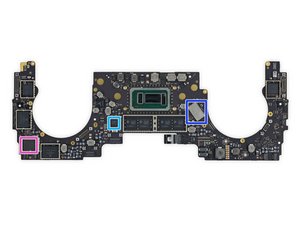
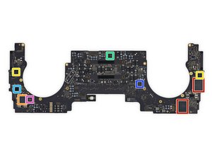
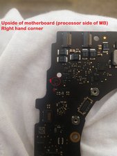
mac book pro 13" A1706. my friend gave it to repair shop for automatic restart issue. but he ruined it returned with no display at all. fan spin is there. but no display no lights. i opened and took out the motherboard. inspected it and found that some components are missing. attaching images of the motherboard. i will really appreciate the help if someone can help what i can do to fix it.. kindly identify the missing components and tell the part numbers. also i would be very thankful if someone could email me the schematics and board view so i can play around.

Block Image

Block Image

Beantwortet! Antwort anzeigen Ich habe das gleiche Problem

Ist dies eine gute Frage?

Bewertung 1
Einen Kommentar hinzufügen

6 Antworten

Gewählte Lösung

Picture 1 is of components on one of the hall effect sensors (there are 2 in this model); these are not listed in the schematic so you will need a donor board to transfer them across (think these are different to the older models). Best to desolder the whole block remaining (raised bit of the board) and for the one on the opposite side too; having one working sensor and one with missing components may be causing the MacBook to think it is asleep.

Picture 2 is U5850 (TMP461 chip) and C5850 (0.1UF 10% 6.3V 0201 capacitor), for the thermal sensor. Looks like the pads have been ripped off for the chip, so you will have to solder wires, and may have difficulty securing the chip. I have an 820-00164 with the TBT thermal sense chip ripped off too, and the fan spins but it doesn't chime, so this can prevent boot.

You may have trouble finding some of the chips on these boards, I'm struggling to get hold of a few FDMF5808A's for a customer with this model...

War diese Antwort hilfreich?

Bewertung 3

4 Kommentare:

i would really appreciate if you could email me board view file

von

You can find the schematic and board view online, just Google the board number 820-00239. I don't distribute them :)

von

thank you for giving chip details. i tried to buy board view but seems like my bad luck is going on. paypal is not working for me. money is getting deducted and refunded back in bank account. but website not getting it.. trying since last three days

von

This is where I get my schematics from... http://laptopserviz.bg

von

Einen Kommentar hinzufügen

Comparing the tear down images, I do not see anything missing. See the original board image here:

https://d3nevzfk7ii3be.cloudfront.net/ig...

War diese Antwort hilfreich?

Bewertung 2

3 Kommentare:

@mayer - take a second look ;-) There is a small transistor missing.

Hint remember what Evan told us...

von

@danj no I don't remember, maybe I'm getting old and can't see well anymore. I did ask Kevin to list a couple of microscopes in the tools section.

von

Don’t feel bad I needed my glasses and a magnifier:-}

I’ll email you tonight with what he said.

von

Einen Kommentar hinzufügen

I think those are No Stuff pads. Yes, that's what a certain company that we must not mention calls them in the schematics. Unfortunately without schematics for this machine, finding what any of those are is going to be heard unless we can find a donor board.

War diese Antwort hilfreich?

Bewertung 1

2 Kommentare:

@tcrs_circuit - Tim, Did you see the small black transistor at the three pads location in the IFIXIT post. It’s missing in the OP’s image. The two on the left I think are test points. It’s a bit odd to have a raised board like this.

von

there is a small cap on the left side of transistor. i think it has to do something with usb type c ports. if you see the opposite side ( toward other side of usb ports) there is a same small raised board.. its hard to figure out what does it do without bard view and schematics

von

Einen Kommentar hinzufügen

Here’s a clear image of the second components location at the bottom right

Block Image

And here is one for the first which is at the top left:

Block Image

Clearly this system had some trauma. Did it get wet?

As the system is so new I don’t know of anyone having board layouts yet to even ID the parts.

War diese Antwort hilfreich?

Bewertung 0

2 Kommentare:

it did not get wet. but someone ripped off those components while opening.

von

Why was the logic board taken out?

At this point I see no out here. Time for a new system :-{

An expensive lesson for someone.

von

Einen Kommentar hinzufügen

Please i need 820-00239-a brd view and schematics

War diese Antwort hilfreich?

Bewertung 0
Einen Kommentar hinzufügen

Hello, I know this is an old post.

Does anyone with more knowledge of the logic board know which chip, or capacitor provides power to the touchbar? One on the logic board, not the one on the touch bar flex cable.

War diese Antwort hilfreich?

Bewertung 0
Einen Kommentar hinzufügen

Antwort hinzufügen

desh raj wird auf ewig dankbar sein.
Seitenaufrufe:

Letzte 24 Stunden: 1

Letzte 7 Tage: 11

Letzte 30 Tage: 29

Insgesamt: 1,653