Einleitung
With all the iPad IC teardowns (thanks Chipworks!), I couldn't help but teardown my household silicon wafer handeling unit from Hine Design Inc. This unit is model # 04300-071. Those of you at home may have a slightly different model number, but if you've seen one you've seen them all right? Hine Design was bought by Asyst Technologies Inc., which was later bought by Crossing Automation. Lets get started!
Was du brauchst
-
-
Here she is in all her beauty! 5 axes of rotation!
-
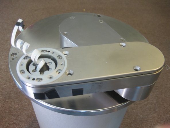
Water and air are pumped through the ports on the bottom of the second image and travel all the way up to the grabbing white arm on top.
-
-
-
Begin by removing the top cover of the white plastic portion of the arm system.
-
Note the small motor on the bottom that rotates the vacuum arm. It uses a purely rubber friction gear with no teeth.
-
-
-
Remove 6 screws on the bottom of the white arm, separating this part of the arm form the metal portion.
-
Separate the vacuum tubes from the white arm and the metal arm linkage. This may seem difficult at first, but give it a little tug and it will come.
-
-
-
While removing the top metal plate of the middle arm linkage, be sure to remove the black electrical tape securing the cover. The electrical tape may not be present on all models.
-
Remove the arm, and then remove the final arm cover.That makes 3 arms removed! I wish I had 3 arms, it would make soldering a much easier task.
-
-
-
-
Here is the Wafer Handling Unit with no arms! I have to admit, there is quite an awkward stench coming from the unit at this point. I am not sure what it is, but its not me this time!
-
Its time to take off the outer skirting! Lets see what inside this beast.
-
-
-
Remove the screws lining the sides of the unit.
-
Wow, its one beautiful piece of equipment inside. Pictures just can't say how pretty the mechanics are inside, but I am sure everyone else will see for themselves when they take apart their Automated Wafer Handling Unit.
-
-
-
The brains inside the unit are just as impressive! It uses an Intel N80C186EB25 16-Bit processor (Digikey)
-
There is also my beloved LM339 Quad Comarator Chip, M74HC32B1 Quad 2-Input OR Gate (ST Micro), Quad 2-Input NAND Gate (Digikey), HM628128BLP SRAM, HIP4081AIP High Frequency Full Bridge FET Driver (Digikey)
-
MAX232CPE RS-232 Driver/Receiver (Maxim), MAX691CPE uP Supervisor (Maxim), LMD18200T 3A Motor Controllers (National), MC74HCT373AN 3-State Non-Inverting Latch (Digikey), MC41A Brushless Motor Controller (Datasheet), CS82C55A Programmable Peripheral Interface
-
One of the FETs appears to have melted the plastic casing, exposing the lead connection on the silicon. This could be why mine stopped working!
-
-
-
Removing one of the side support beams, I discovered why this thing is so dang heavy. The support beam is a 1/4 inch piece of steel.
-
There appears to be 3 motors driving several gears and screw drives. There are also several Hall Effect sensors and buttons used for measuring the extreme maximum and minimum extension of the lifting arm.
-
This motor (2nd image) rotates the second arm linkage.
-
-
-
The 2 arm motors are DC Brushed motors and each of them have a Dynamics Research Corp. Encoder with Model # F21AH4ECB43-2540Z330.
-
-
-
Remove the bottom plate with the sensor, air, water, and vacuum connectors. Then remove the 4 legs, which completely removes the bottom metal plate. Finally, remove the bottom steel base. Be careful in this step, the screw drives get squirmy here! The lifter arm motor should slide out easily now.
-
The unit finally drew blood! The screws on the base can be very tight. Take caution when loosening them, your hand may slip and the steel does not give much vs my flesh!
-
-
-
Remove the screw drive.
-
Remove the top plate. The screw drive lifts the entire motor unit up and down inside the unit, which slides along the two parallel bars shown here.
-
At this point, just start taking out every screw you can see, removing parts that come loose!
-
-
-
And now, the beloved final picture of all the parts! Hope you enjoyed the teardown!
-


3 Kommentare
Zitat von Aurimas:
What the !%^* is this thing and what it does?
It is exactly what the title says: it handles silicon wafers (the giant circular wafers full of processors and such prior to packaging—hence the reference to the iPad processor exhibition). Those things should not be transported by hand and are usually moved with a machine such as this.
I can't see where is the fifth axis of motion. It should be an Yaw axis, but I can't imagine where the drive is placed.
All axes here are Z motion, Theta and radial motion and flipping Roll axis. Do we talking about Yaw axis? Wnere is the drive of this axis? On the first photo I see that it seems to be realy 5 axes handler. Another question - what is purpose of both small lead screws connected with R-Theta belt reducer? Is that some kind of limitation and hardstops between dependable axes R and Theta?
regards
It looks like the 5th axis is roll. Look at the first picture in step 2, and compare the position of the white arm with the first picture of steps 1 and 3. It is clear that the axis rotates in line with the motor we can see.
I would guess that one of the jobs of this robot was to pick up a wafer from a flat position, rotate it 90 degrees and then place it in a vertical carrier, but cody might know more.