Einleitung
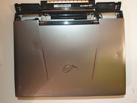
Use this guide if you need to replace the motherboard in your Asus ROG G752V.
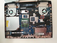
The motherboard acts as a single platform to connect all of the parts of a computer together. It serves as the computer's nervous system.
Reasons to replace your motherboard:
- Physical damage to the board
- If peripherals work intermittently, try using different peripherals in different ports to see if it is a bad port, bad peripheral, or bad motherboard
- Computer does not post (No bios on startup)
- Upgrades
Before beginning, make sure to power off your computer. Disconnect it from any external power source. Remove dust build-up with a dust blower.
Was du brauchst
-
In diesem Schritt verwendetes Werkzeug:Tweezers$4.99
-
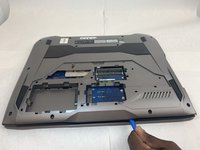
Pick out all 11 rubber plugs off of the back cover with a pair of tweezers.
-
-
-
Using the Phillips #0 screwdriver, unscrew all twelve 5.2 mm screws on the back of the laptop.
In my case, the 4 screws alongside the touchpad are smaller than the others.
-
-
-
Using the Phillips #00 screwdriver, remove the six 5.2 mm screws under the service cover.
-
-
-
Using your hands, pull the optical drive out.
You will need a small safety pin or similar to release the CD drive tray so it can open. Look for a small hole and insert the pin into the hole and push, it should normally open the tray.
Once open, look for 3 small screws that are attached to the cover. These have to be removed so the cover can come off.
-
-
-
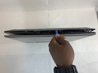
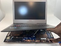
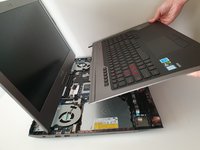
Use the iFixit Opening Tool to pry apart the back panel from the main body of the laptop.
-
-
-
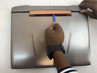
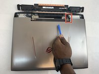
Remove the hinge on the back of the laptop cover using the iFixit Opening Tool. The piece should pop off.
-
-
-
Using an ESD safe tool, detach all 3 ribbon cables securing the keyboard to the laptop.
Do you do the same thing in Reverse lift the flap up place the ribbon down and then it's snaps?
-
-
-
-
Once the cables are detached, lift the keyboard about 2 inches up and remove it from the rest of the body.
-
-
-
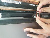
Disconnect the battery cable from its motherboard socket by gently pulling it towards the left of the socket.
-
-
-
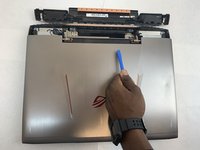
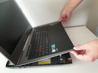
Remove two 5.8 mm screws holding the screen and the laptop located at the hinge.
-
Remove the screen.
In my case, 6 x M2.4x9,6mm screws near the center - indicated with X stamp - and 2 x M1,9x6,6mm screws, 1 on the left hand side and the other on the right hand side.
Mine same as Jonathan’s. Total of 8 screws to remove the screen
Same here, 8 screws. Also… must disconnect screen!
-
-
-
Remove the four 5.8 mm screws securing the battery to the laptop.
-
-
-
Use your hands to remove the battery.
The second set of wires going to the battery (shown on the right side between the tech's thumb and forefinger) are attached to a strip glued to the back of the battery. I believe it is a temperature sensor of some kind. Carefully peel it off the old battery, being careful not to bend it and press it to onto the new battery. There are two holes in the sensor strip, on at the right in the corner, another at the left end in the center. On the battery, there are two very small, hard to see alignment points to fit into those holes.
-
-
-
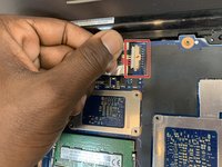
Unscrew one 3mm Philips #00 screw on the wireless card.
Throughout guides, check to make sure the markup matches the bullets.
Also, make sure to remove locate steps—what do you want the user to do with the wireless card?
-
-
-
Using your hands, unlatch the wireless card by pulling it out toward the screen.
How should I use my hand?
What card type is that? What can replace it?
I replaced my M.2 wifi card with a new Intel AX210.
Very good upgrade!
I now have WiFi6 and Bluetooth 5.2
You should probably go ahead and order new IPEX 4 MHF4 Antenna 2.4GHz 5GHz 3dBi Internal Laptop WiFi Antenna for M.2. - just so you have them. To replace the antennas, there are 4 screws at the bottom of the screen (hidden behind plastic covers). Once you get those screws out you will be able to pop the bezel off starting at the left and right sides on the top. After you get the bezel off, disconnect the camera module then unscrew the lcd mounts and fold the lcd away from the shell so that you can run the new antenna. Mind how they routed and taped the old antenna wires and do the same with the new antenna.
-
-
-
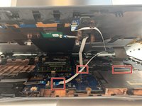
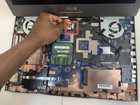
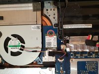
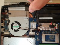
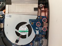
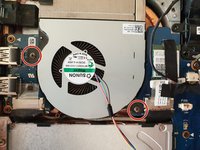
Unscrew and remove the three 5.8mm screws on the small circuit board to the right of the right side fan with a Phillips #00 screwdriver.
-
Lift up the small circuit board covering the fan and put it aside.
-
-
-
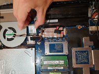
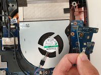
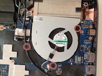
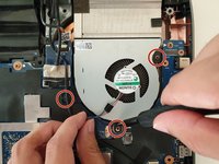
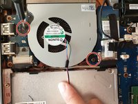
Using a Phillips #00 screwdriver, remove the three 5.2 mm screws that connect the fan to the motherboard.
-
-
-
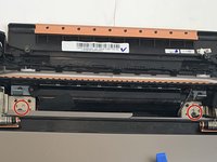
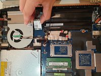
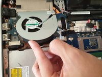
Using a Phillips #00 screwdriver, remove the two 5.8mm screws that connect the left fan to the motherboard.
-
-
-
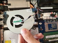
With your hands, carefully lift the left fan and unlatch the fan from the motherboard.
-
-
-
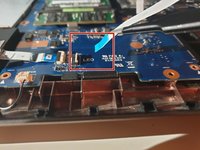
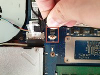
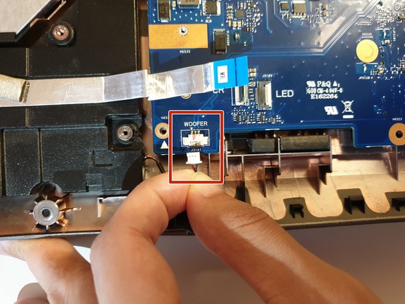
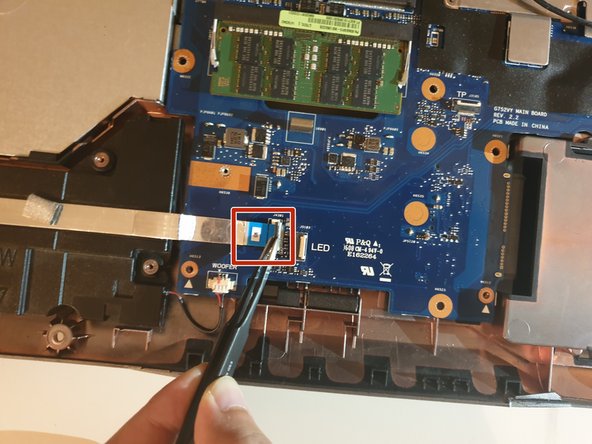
Using your hand, detach the Woofer Cable.
-
-
-
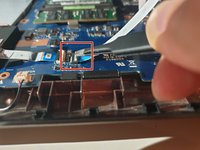
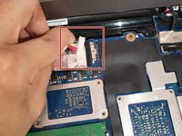
Using an ESD safe tool, first unlatch the ZIF connector clasp and then pull the cord disconnecting the SD card reader.
-
-
-
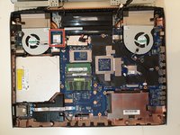
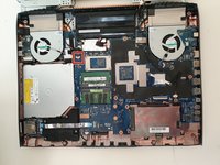
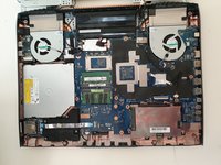
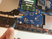
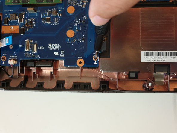
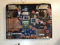
Unscrew eighteen 5.8 mm screws from the motherboard with a Phillips #00 screwdriver.
-
-
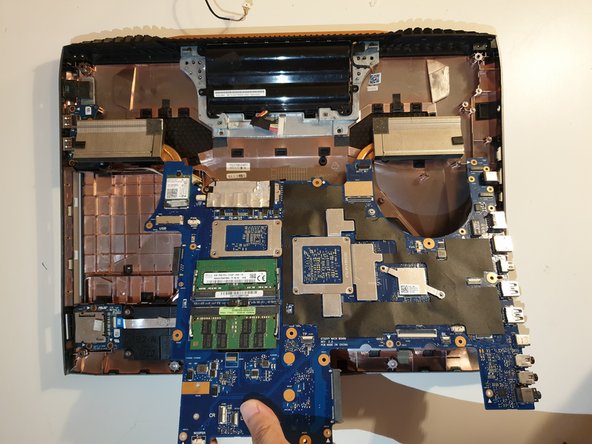
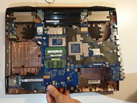
-
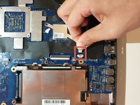
Using your hands, unlatch the motherboard by lifting it up directly above the laptop.
-


To reassemble your device, follow these instructions in reverse order.
To reassemble your device, follow these instructions in reverse order.
Rückgängig: Ich habe diese Anleitung nicht absolviert.
3 weitere Personen haben diese Anleitung absolviert.
Team

Embry-Riddle Aeronautical University, Team S2-G36, Watkins Fall 2019 Mitglied von Embry-Riddle Aeronautical University, Team S2-G36, Watkins Fall 2019
ERAU-WATKINS-F19S2G36
4 Mitglieder
7 Anleitungen geschrieben
Ein Kommentar
This guide is full of mistakes, please redo it !!! not good at all.
The wifi card can stay on the mobo, and there is not always teh same screw size... Some screws can stay on the board or the place shown does not exists.... show the routing of the cables also, behind the screen....