Einleitung
Folge dieser Anleitung, um die Joysticks an einem Sony PlayStation 5 DualSense Controller zu tauschen.
Was du brauchst
-
-
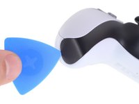
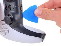
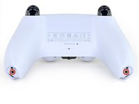
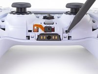
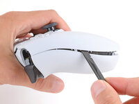
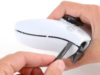
Stecke ein Plektrum unter die untere rechte Ecke der Abdeckung, um die Clips zu lösen, mit denen sie befestigt ist.
-
-
-
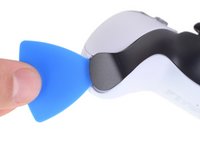
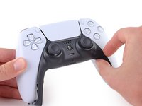
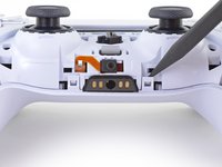
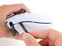
Schiebe das Plektrum an der unteren rechten Kante entlang, um die Clips zu lösen, die die Abdeckung festhalten.
-
-
-
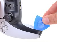
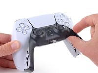
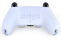
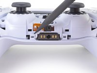
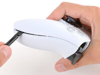
Stecke ein Plektrum unter die untere linke Ecke der Abdeckung, um die Clips zu lösen, mit denen sie befestigt ist.
-
-
-
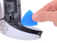
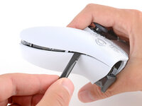
Schiebe das Plektrum an der unteren linken Kante entlang, um die Clips zu lösen, die die Abdeckung festhalten.
-
-
-
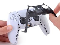
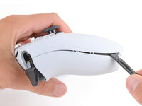
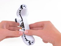
Hebe die Abdeckung mit deinen Fingern an der unteren Kante an, um die restlichen Clips zu lösen.
-
Hebe die Abdeckung über die Joysticks, um sie zu entfernen.
-
-
-
Fasse den Kontroller mit einer Hand und halte den linken Auslöser mit dem Daumen gedrückt.
-
Setze das flache Ende des Spudgers mit der anderen Hand zwischen die L1 und L2 Tasten ein.
-
Heble die L1 Taste mit dem Spudger behutsam vom Kontroller weg, halte dabei den Finger darüber, damit die Taste nicht davonspringen kann.
-
-
-
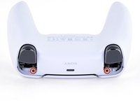
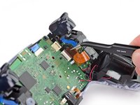
Entferne die beiden 6,4 mm Kreuzschlitzschrauben, die die unteren Enden des Gehäuseunterteils fixieren.
-
-
-
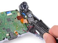
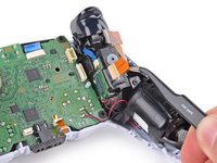
Löse die beiden Clips links und rechts von der Kopfhörerbuchse mit der Spitze des Spudgers.
-
-
-
-
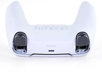
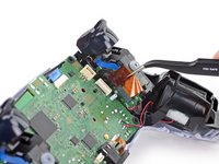
Entferne die beiden 6,4 mm Kreuzschlitzschrauben, die die unteren Enden des Gehäuseunterteils fixieren.
-
-
-
Löse die beiden Clips links und rechts von der Kopfhörerbuchse mit der Spitze des Spudgers.
-
-
In diesem Schritt verwendetes Werkzeug:Tweezers$4.99
-
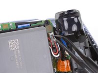
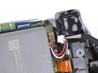
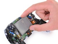
Trenne das Akkukabel mit einer Pinzette oder deinen Fingern vom Motherboard.
-
-
In diesem Schritt verwendetes Werkzeug:Tweezers$4.99
-
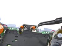
Ziehe das Kabel des unteren Mikrofons mit einer Pinzette oder deinen Fingern aus dem Anschluss auf dem Motherboard.
-
-
-
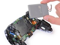
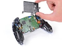
Entferne die 6,4 mm Kreuzschlitzschraube, die die Halterung für den Akku fixiert.
-
-
-
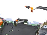
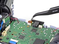
Löse das Kabel der rechten Tasteneinheit, indem du es mit einer Pinzette oder deinen Fingern aus dem Anschluss auf dem Motherboard ziehst.
-
-
-
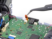
Greife die Lasche des Kabels an der rechten Tasteneinheit mit einer Pinzette oder deinen Fingern und trenne es von der Tasteneinheit.
-
Entferne das Kabel.
-
-
-
Löse das Kabel der linken Tasteneinheit, indem du es mit einer Pinzette oder deinen Fingern aus dem Anschluss auf dem Motherboard ziehst.
-
-
-
Greife die Lasche des Kabels an der linken Tasteneinheit mit einer Pinzette oder deinen Fingern und trenne es von der Tasteneinheit.
-
Entferne das Kabel.
-
-
-
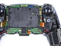
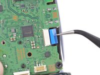
Ziehe das Kabel des oberen Mikrofons mit einer Pinzette oder deinen Fingern aus dem Anschluss auf dem Motherboard.
-
-
-
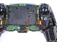
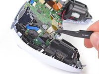
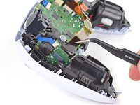
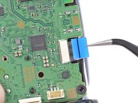
Ziehe das Kabel des Touchpads mit einer Pinzette oder deinen Fingern aus dem Anschluss auf dem Motherboard.
-
-
-
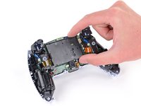
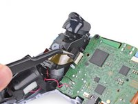
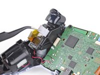
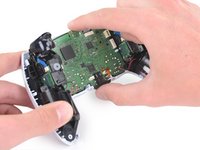
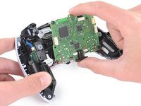
Führe die Joysticks vorsichtig durch die Gehäusevorderseite und hebe das Motherboard heraus.
-
-
-
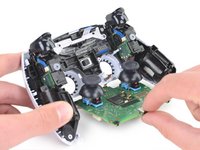
Drehe den Controller und die Hauptplatine um.
-
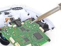
Entlöte die Kabel der Vibrationsmotoren mit Hilfe eines Lötkolbens von der Hauptplatine:
-
Zwei rote Kabel
-
Zwei schwarze Kabel
-
-
-
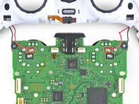
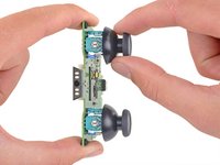
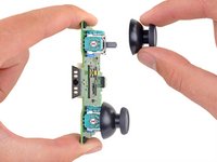
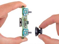
Ziehe die Joystick-Abdeckungen gerade von den Joystick-Baugruppen ab.
-
Nun bleibt nur noch das Mainboard übrig.
-
-
In diesem Schritt verwendetes Werkzeug:Desoldering Pump$3.99
-
Benutze den Lötkolben und eine Entlötpumpe, um die vierzehn Verbindungen an jedem Joystick zu entlöten.
-


Um das Gerät wieder zusammenzusetzen, befolge die oberen Schritte in umgekehrter Reihenfolge.
Entsorge deinen Elektromüll sachgerecht.
Hat die Reparatur nicht ganz geklappt? Versuche es mit ein paar grundständigen Lösungen, ansonsten findest du in unserem Forum Hilfe bei der Fehlersuche.
Um das Gerät wieder zusammenzusetzen, befolge die oberen Schritte in umgekehrter Reihenfolge.
Entsorge deinen Elektromüll sachgerecht.
Hat die Reparatur nicht ganz geklappt? Versuche es mit ein paar grundständigen Lösungen, ansonsten findest du in unserem Forum Hilfe bei der Fehlersuche.
Rückgängig: Ich habe diese Anleitung nicht absolviert.
48 weitere Personen haben diese Anleitung absolviert.
Besonderer Dank geht an diese Übersetzer:innen:
100%


Diese Übersetzer:innen helfen uns, die Welt zu reparieren! Wie kann ich mithelfen?
Hier starten ›

26 Kommentare
How do you differentiate a real joystick part from fake ones? Since in my situation i can't order straight from sony.
I would suggest getting a PS4 Dualshock controller from the classifieds since there's a pile of them available for cheap and take the analogue stick from there.