Zum Hauptinhalt wechseln
Gemeinsam reparieren - Jetzt registrieren

GoPro Hero+ LCD Image Sensor Replacement

Was du brauchst

  1. GoPro Hero+ LCD Image Sensor Replacement, Back Panel: Schritt 1, Bild 1 von 2 GoPro Hero+ LCD Image Sensor Replacement, Back Panel: Schritt 1, Bild 2 von 2
    • Be sure to power off the GoPro before you start disassembly.

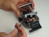
    • Pop up and pull back on the clip to remove the screen cover and expose the back panel with the touchscreen.

    Frag FixBot

    Kommentar hinzufügen

  2. GoPro Hero+ LCD Image Sensor Replacement: Schritt 2, Bild 1 von 2 GoPro Hero+ LCD Image Sensor Replacement: Schritt 2, Bild 2 von 2
    • Use the metal spudger to pry around the perimeter of the panel.

    • Pry the panel upwards by inserting the metal spudger into the corner crease between the panel and camera shell.

    Frag FixBot

    Kommentar hinzufügen

  3. GoPro Hero+ LCD Image Sensor Replacement: Schritt 3, Bild 1 von 2 GoPro Hero+ LCD Image Sensor Replacement: Schritt 3, Bild 2 von 2
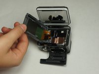
    • Pry around the panel to ensure it is not attached to the device.

    • Move the panel to the side so you can access the internal components.

    • The panel is still attached to the rest of the device with a ribbon cable, so be sure to not tear or damage the cable.

    Frag FixBot

    Kommentar hinzufügen

  4. GoPro Hero+ LCD Image Sensor Replacement, Battery: Schritt 4, Bild 1 von 1
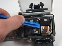
    • Peel back the rear panel ribbon cable that is adhered to the battery until it is completely separated from the battery.

    • Be careful of metal contacts on strip; they can be sharp.

    Frag FixBot

    Kommentar hinzufügen

  5. GoPro Hero+ LCD Image Sensor Replacement: Schritt 5, Bild 1 von 1
    In diesem Schritt verwendetes Werkzeug:
    Tweezers
    $4.99
    • Using tweezers, peel off the copper tape on the right side of the battery.

    Frag FixBot

    Kommentar hinzufügen

  6. GoPro Hero+ LCD Image Sensor Replacement: Schritt 6, Bild 1 von 2 GoPro Hero+ LCD Image Sensor Replacement: Schritt 6, Bild 2 von 2
    • Place the plastic opening tool at one of the edges of the battery then pry until the battery is removed from the GoPro.

    Frag FixBot

    Kommentar hinzufügen

  7. GoPro Hero+ LCD Image Sensor Replacement: Schritt 7, Bild 1 von 1
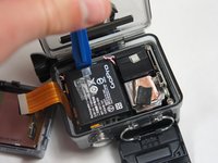
    • Use a pair of tweezers to disconnect the battery connector from the motherboard.

    • Gently pull the battery off the motherboard. Pulling vertically off the motherboard will give a clean release.

    Frag FixBot

    Kommentar hinzufügen

  8. GoPro Hero+ LCD Image Sensor Replacement, MicroSD/Micro USB Port Assembly: Schritt 8, Bild 1 von 3 GoPro Hero+ LCD Image Sensor Replacement, MicroSD/Micro USB Port Assembly: Schritt 8, Bild 2 von 3 GoPro Hero+ LCD Image Sensor Replacement, MicroSD/Micro USB Port Assembly: Schritt 8, Bild 3 von 3
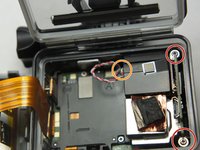
    • Remove the two 6 mm Phillips #00 screws.

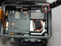
    • Remove the single 4 mm Phillips #000 screws.

    Frag FixBot

    Kommentar hinzufügen

  9. GoPro Hero+ LCD Image Sensor Replacement: Schritt 9, Bild 1 von 1
    • Remove the image sensor from the camera.

    • You do not have to unplug the black box to remove the USB/SD chip.

    Frag FixBot

    Kommentar hinzufügen

  10. GoPro Hero+ LCD Image Sensor Replacement: Schritt 10, Bild 1 von 1
    In diesem Schritt verwendetes Werkzeug:
    Tweezers
    $4.99
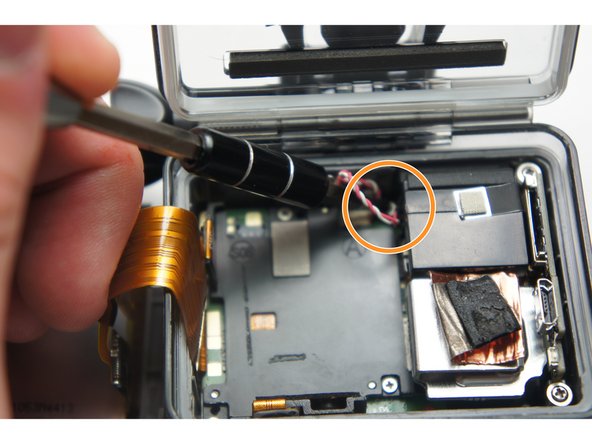
    • Grab the edge of the ribbon cable with the tweezers and gently pull until the cable is disconnected from the motherboard.

    • Be careful when removing the ribbon cable. You must pull gently or you can rip the ribbon off of its contacts.

    Frag FixBot

    Kommentar hinzufügen

  11. GoPro Hero+ LCD Image Sensor Replacement: Schritt 11, Bild 1 von 1
    • Gently lift the microSD/Micro USB assembly up and out of the device.

    Frag FixBot

    Kommentar hinzufügen

  12. GoPro Hero+ LCD Image Sensor Replacement, Image Sensor: Schritt 12, Bild 1 von 1
    • Use your fingers and gently pull out the sensor from the motherboard by slowly and gradually pulling up on the image sensor box.

    • Do not yank on the image sensor, it can rip out the wiring or damage the motherboard.

    Frag FixBot

    Kommentar hinzufügen

Abschluss

To reassemble your device, follow these instructions in reverse order.

Rückgängig: Ich habe diese Anleitung nicht absolviert.

Team

USF Tampa, Team 2-4, Blackwell Fall 2015 Mitglied von USF Tampa, Team 2-4, Blackwell Fall 2015

USFT-BLACKWELL-F15S2G4

4 Mitglieder

20 Anleitungen geschrieben

0 Kommentare zur Anleitung

Kommentar hinzufügen

Seitenaufrufe:

Letzte 24 Stunden: 0

Letzte 7 Tage: 6

Letzte 30 Tage: 45

Insgesamt: 2,121