Diese Version enthält möglicherweise inkorrekte Änderungen. Wechsle zur letzten geprüften Version.
Was du brauchst
-
-
Beginne mit dem Entfernen der silbernen Kunststoffvorderseite der Kamera mit einem Kunststoff Öffnungswerkzeug. Setze das Kunststoff-Öffnungswerkzeug in die Mitte jeder Kante ein und hebe die Rasten an, mit denen die Kameravorderseite befestigt ist.
-
Die sieben Befestigungsrasten sind rot markiert.
-
-
Dieser Schritt ist noch nicht übersetzt. Hilf mit, ihn zu übersetzen!
-
Remove the three 8 mm Phillips #000 screws on each corner of the camera.
-
Remove the single 4 mm Phillips #000 screw on the bottom left corner of the camera.
-
-
Dieser Schritt ist noch nicht übersetzt. Hilf mit, ihn zu übersetzen!
-
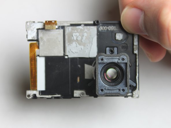
To remove the motherboard assembly from the camera casing, use the plastic opening tool on the lens side of the camera to pry the motherboard assembly out of the camera housing.
-
To avoid breaking the plastic on the lens side of the camera (see photo), pry along the edges near the corners.
-
-
Dieser Schritt ist noch nicht übersetzt. Hilf mit, ihn zu übersetzen!
-
Remove the four 8 mm Phillips #000 screws securing the camera sensor assembly.
-
-
Dieser Schritt ist noch nicht übersetzt. Hilf mit, ihn zu übersetzen!
-
To remove the sensor assembly, simply peel off the lens towards the attached ribbon cable.
-
The sensor has ribbon cables running to the motherboard via a black rectangular connector.
-
To remove the sensor, use the spudger to pry up each side, Then, lift the connector straight up from its socket.
-
With the old camera sensor assembly removed, you can now replace it with a new sensor.
-
-
Dieser Schritt ist noch nicht übersetzt. Hilf mit, ihn zu übersetzen!
-
Remove the three 8 mm Phillips #000 screws securing the Hero port to the motherboard.
-
-
-
Dieser Schritt ist noch nicht übersetzt. Hilf mit, ihn zu übersetzen!
-
Locate the copper-colored ribbon cables connecting the Hero Port to the motherboard.
-
To remove the connector, use tweezers or a spudger, pry up each side of the connector. Then, lift the connector straight up from it's socket.
-
-
Dieser Schritt ist noch nicht übersetzt. Hilf mit, ihn zu übersetzen!
-
To remove the free port, simply slide it out from the left side of the camera. It should come out with slight coercion.
-
This piece can be replaced, fixed, or set aside for further tear-down of the GoPro.
-
Pictured left is the port when separated from the motherboard.
-
-
Dieser Schritt ist noch nicht übersetzt. Hilf mit, ihn zu übersetzen!
-
Use a pair of tweezers to disconnect the ribbon cable from the ZIF connector by flipping up the black retaining flap. You should then be able to pull the cable free.
-
Once the ribbon cable is disconnected, you can remove the black plastic bracket which holds the camera lens.
-
-
Dieser Schritt ist noch nicht übersetzt. Hilf mit, ihn zu übersetzen!
-
Once the camera assembly has been removed, you can begin separating the motherboard assembly from the camera housing.
-
-
Dieser Schritt ist noch nicht übersetzt. Hilf mit, ihn zu übersetzen!
-
Flip the motherboard assembly and camera housing over so you can access the back of the motherboard.
-
Look for the white connector that has two wires that lead from the mother board to the battery compartment in the camera housing.
-
Using the metal tweezers, pull upward on the connector to disconnect the clip.
-
-
Dieser Schritt ist noch nicht übersetzt. Hilf mit, ihn zu übersetzen!
-
With the connector removed you can now set the camera housing aside and work on the motherboard.
-
-
Dieser Schritt ist noch nicht übersetzt. Hilf mit, ihn zu übersetzen!
-
Flip the motherboard over.
-
Remove the single 8 mm Phillips #000 screw.
-
-
Dieser Schritt ist noch nicht übersetzt. Hilf mit, ihn zu übersetzen!
-
Flip the motherboard over. The speaker assembly should be loose and only connected by two wires leading to a white connector.
-
Using the metal tweezers, pull upwards to disconnect the connector from its port.
-
-
Dieser Schritt ist noch nicht übersetzt. Hilf mit, ihn zu übersetzen!
-
Once disconnected from the motherboard, the speaker assembly can be removed.
-
-
Dieser Schritt ist noch nicht übersetzt. Hilf mit, ihn zu übersetzen!
-
With the speaker assembly removed, you can now replace the motherboard.
-


Rückgängig: Ich habe diese Anleitung nicht absolviert.
28 weitere Nutzer:innen haben diese Anleitung absolviert.
Team

USF Tampa, Team 2-1, Blackwell Fall 2015 Mitglied von USF Tampa, Team 2-1, Blackwell Fall 2015
USFT-BLACKWELL-F15S2G1
4 Mitglieder
20 Anleitungen geschrieben
11 Kommentare
Do step 9 before step 6. It's near impossible to get the middle screw out in the order the guide presents. There's also a screw that isn't mentioned that needs to be removed in order to complete step 9. You can see the screw in step 6's picture right above the QR bar code.
Hi team,
How would you secure the flex cables, next to the power connector, back to the motherboard?
Did you ever get an answer as i have the same problem
Same problem
gelmi -
Anything on this yet?