Was du brauchst
-
-
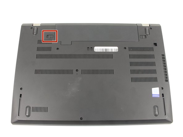
Drücke den Schieber an der rechten Seite des Akkus nach rechts und drücke gleichzeitig den Akku nach oben hinaus
-
-
-
Löse die acht 3,3 mm langen Kreuzschlitzschrauben #00 an der Bodenplatte.
-
-
-
Nimm ein geeignetes Werkzeug, z.B. einen Jimmy, setze es in die Naht am Computer ein und lasse es rundum laufen. Verdrehe es ab und zu, damit sich die Rasten lösen.
-
-
-
Entferne die fünf 3,7 mm langen Kreuzschlitzschrauben #00, mit denen der interne Akku befestigt ist.
-
-
-
Löse die fünf 4,6 mm langen Kreuzschlitzschrauben €00, mit denen der Lüfter und die Wärmeleitröhre befestigt sind.
-
-
Schritt 12
Achtung: Die Schritte 12-14 stammen von einer Anleitung, die derzeit bearbeitet wird.
Dieser Schritt ist noch nicht übersetzt. Hilf mit, ihn zu übersetzen!
-
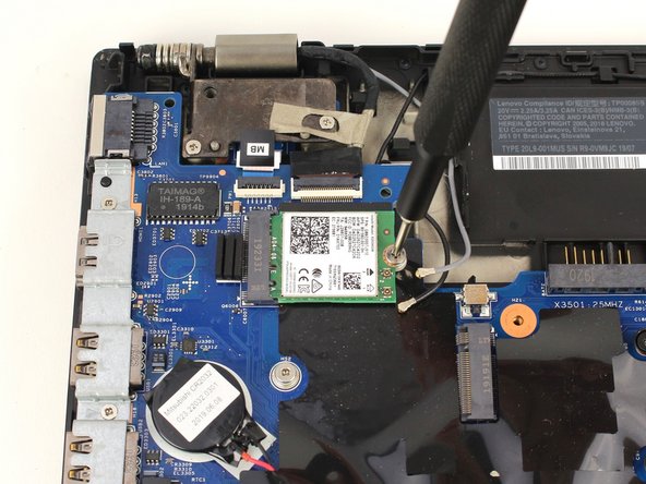
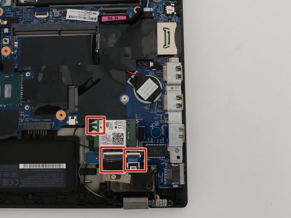
Using a spudger, pop off the gray and black coaxial cables from the Wi-Fi card.
-
-
-
Dieser Schritt ist noch nicht übersetzt. Hilf mit, ihn zu übersetzen!
-
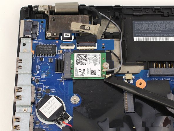
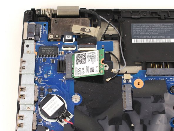
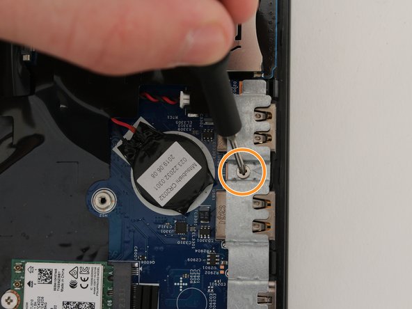
Using a Phillips #00 screwdriver, remove the 3.6 mm screw from the Wi-Fi card.
-
-
Dieser Schritt ist noch nicht übersetzt. Hilf mit, ihn zu übersetzen!
-
Slide the Wi-Fi card out from the socket on the motherboard.
-
-
Schritt 15
Achtung: Die Schritte 15-17 stammen von einer Anleitung, die derzeit bearbeitet wird.
Dieser Schritt ist noch nicht übersetzt. Hilf mit, ihn zu übersetzen!
-
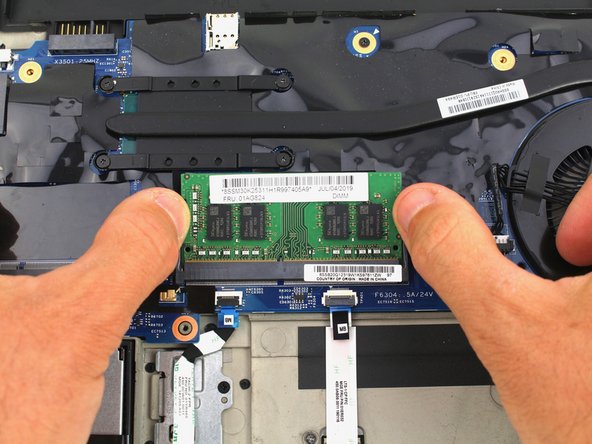
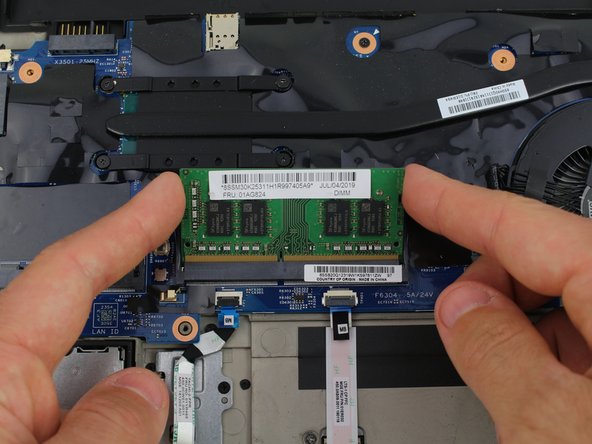
Pull the two tabs on either side of the RAM card outwards with your fingers.
-
-
Dieser Schritt ist noch nicht übersetzt. Hilf mit, ihn zu übersetzen!
-
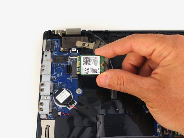
Pull the Wi-Fi card out from the port by the edges of the card.
-
-
Dieser Schritt ist noch nicht übersetzt. Hilf mit, ihn zu übersetzen!
-
Remove the RAM module from the laptop.
-
Repeat the same process for the second RAM module if your computer included one.
-
-
Dieser Schritt ist noch nicht übersetzt. Hilf mit, ihn zu übersetzen!
-
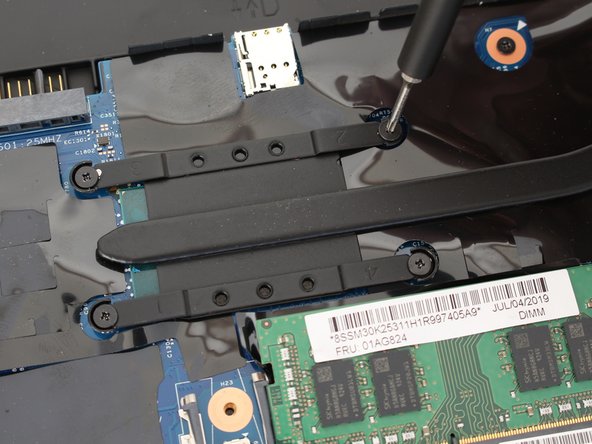
Use a Phillips #00 screwdriver to unscrew the three 3.3 mm captive screws securing the keyboard.
-
-
Dieser Schritt ist noch nicht übersetzt. Hilf mit, ihn zu übersetzen!
-
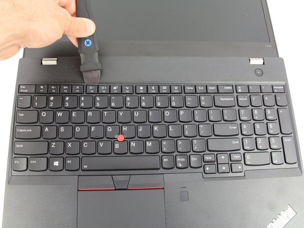
Use a Jimmy to pry under the top left corner of the keyboard.
-
-
Dieser Schritt ist noch nicht übersetzt. Hilf mit, ihn zu übersetzen!
-
Continue prying along the top edge of the keyboard, releasing the clips as you go.
-
Once the top edge has been fully released, grab the top edge and hinge the keyboard upwards on the bottom edge.
-
-
Dieser Schritt ist noch nicht übersetzt. Hilf mit, ihn zu übersetzen!
-
Pull the keyboard away from you, releasing the tabs along the bottom edge.
-
Flip the keyboard over to rest face down over the trackpad.
-
-
Dieser Schritt ist noch nicht übersetzt. Hilf mit, ihn zu übersetzen!
-
Use a spudger to lift up the two black, hinged locking flaps on the ZIF connectors on the motherboard.
-
-
Dieser Schritt ist noch nicht übersetzt. Hilf mit, ihn zu übersetzen!
-
Use a pair of blunt nose tweezers to pull the two keyboard ribbon cables out from the ZIF connectors.
-
-
Dieser Schritt ist noch nicht übersetzt. Hilf mit, ihn zu übersetzen!
-
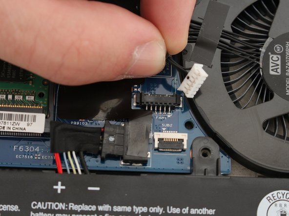
Disconnect all the attached cables.
-
-
Dieser Schritt ist noch nicht übersetzt. Hilf mit, ihn zu übersetzen!
-
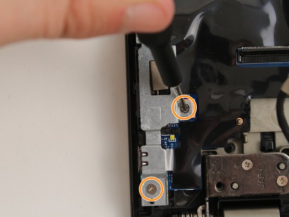
Using a Phillips #00 screwdriver, unscrew the three 3.3 mm motherboard screws.
-
Using a Phillips #00 screwdriver, take out the port clamps and the three 3.6 mm screws.
-
-
Dieser Schritt ist noch nicht übersetzt. Hilf mit, ihn zu übersetzen!
-
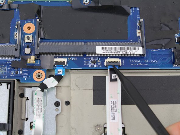
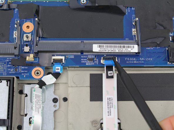
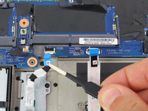
Flip up the two ZIF cables for the trackpad and fingerprint sensor with the pointed end of a plastic spudger.
-
-
Dieser Schritt ist noch nicht übersetzt. Hilf mit, ihn zu übersetzen!
-
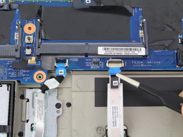
Pull out the two ribbon cables with a pair of blunt nose tweezers.
-
-
Dieser Schritt ist noch nicht übersetzt. Hilf mit, ihn zu übersetzen!
-
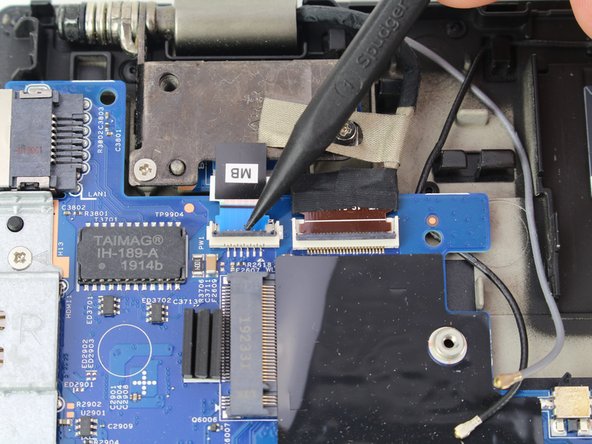
Using a spudger, flip up the locking tabs of the two ZIF connectors on the upper left corner of the motherboard.
-
Pull out each of the ribbon cables using a pair of blunt nose tweezers.
-
-
Dieser Schritt ist noch nicht übersetzt. Hilf mit, ihn zu übersetzen!
-
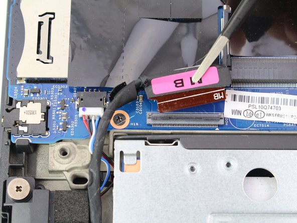
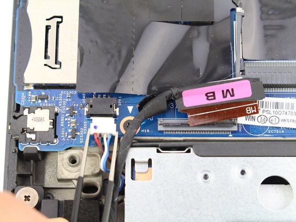
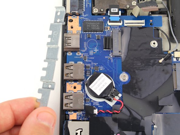
Flip up the locking tab of the ZIF connector on the bottom left of the motherboard.
-
Pull out the ribbon cable and speaker cable from their connectors using a pair of blunt nose tweezers.
-
-
Dieser Schritt ist noch nicht übersetzt. Hilf mit, ihn zu übersetzen!
-
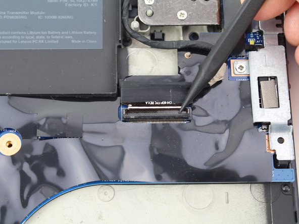
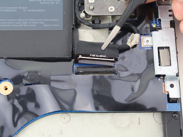
Using a spudger, flip up the locking tab of the ZIF connector in the top right corner of the motherboard.
-
Pull the ribbon cable out from the connector with a pair of blunt nose tweezers.
-
-
Dieser Schritt ist noch nicht übersetzt. Hilf mit, ihn zu übersetzen!
-
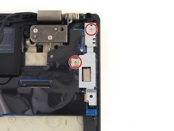
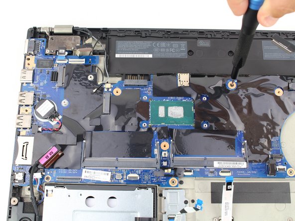
Using a Phillips #00 screwdriver, remove the four 3.6 mm screws holding down the port brackets on the right and left sides of the motherboard.
-
-
Dieser Schritt ist noch nicht übersetzt. Hilf mit, ihn zu übersetzen!
-
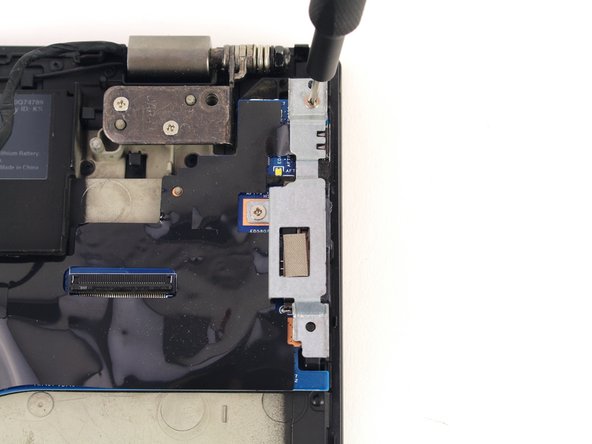
Pull off each of the port brackets.
-
-
Dieser Schritt ist noch nicht übersetzt. Hilf mit, ihn zu übersetzen!
-
Remove the two 3.3 mm screws from the motherboard with a Phillips #00 screwdriver.
-
-
Dieser Schritt ist noch nicht übersetzt. Hilf mit, ihn zu übersetzen!
-
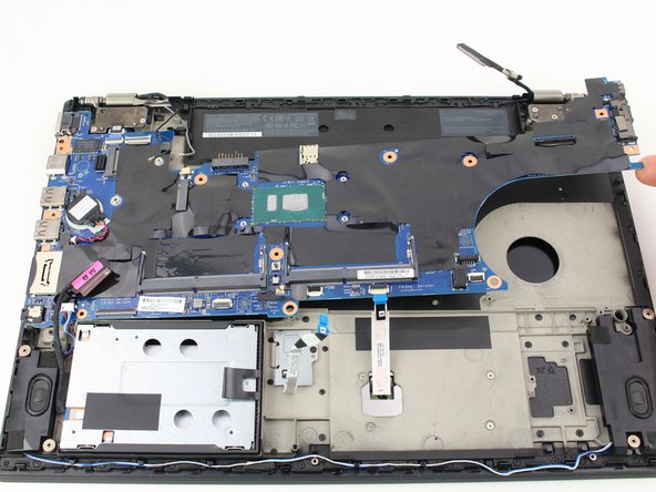
Lift up and remove the motherboard.
-
If your replacement motherboard does not include a CMOS battery, you may need to move it over from your old motherboard. You can follow this CMOS Battery Replacement guide if you need help!
-


Team

Cal Poly, Team S18-G6, White Winter 2020 Mitglied von Cal Poly, Team S18-G6, White Winter 2020
CPSU-WHITE-W20S18G6
4 Mitglieder
24 Anleitungen geschrieben