Diese Version enthält möglicherweise inkorrekte Änderungen. Wechsle zur letzten geprüften Version.
Was du brauchst
-
KaufenIn diesem Schritt verwendetes Werkzeug:P5 Pentalobe Screwdriver Retina MacBook Pro and Air$5.99
-
Entferne die folgenden zehn Schrauben:
-
Zwei 8 mm 5-Point Pentalobe Schrauben
-
Acht 2,5 mm 5-Point Pentalobe Schrauben
-
-
-
Löse das Gehäuseunterteil vom Air, indem du mit den Fingerspitzen zwischen Display und Gehäuse gehst und es nach oben ziehst.
-
Entferne das Gehäuseunterteil und lege es beiseite.
-
-
Dieser Schritt ist noch nicht übersetzt. Hilf mit, ihn zu übersetzen!
-
Use the flat end of a spudger to pry both short sides of the battery connector upward to disconnect it from its socket on the logic board.
-
Bend the battery cable slightly away from the logic board so the connector will not accidentally contact its socket.
-
-
Dieser Schritt ist noch nicht übersetzt. Hilf mit, ihn zu übersetzen!
-
Remove the single 2.9 mm T5 Torx screw securing the SSD to the logic board.
-
-
Dieser Schritt ist noch nicht übersetzt. Hilf mit, ihn zu übersetzen!
-
Use a spudger to help lift the free end of the SSD just enough to grab it with your other hand.
-
Pull the drive straight out of its socket and remove it from the logic board.
-
-
Dieser Schritt ist noch nicht übersetzt. Hilf mit, ihn zu übersetzen!
-
Use the flat end of a spudger to pry the I/O board cable connector upward out of its socket on the I/O board.
-
-
Dieser Schritt ist noch nicht übersetzt. Hilf mit, ihn zu übersetzen!
-
While gently pulling the I/O board cable upward near its connection to the logic board, use the tip of a spudger to pry upward on alternating sides of the connector to help "walk" it out of its socket.
-
Remove the I/O board cable.
-
-
Dieser Schritt ist noch nicht übersetzt. Hilf mit, ihn zu übersetzen!
-
Use the tip of a spudger to carefully flip up the retaining flap on the fan cable ZIF socket.
-
-
Dieser Schritt ist noch nicht übersetzt. Hilf mit, ihn zu übersetzen!
-
Remove the following three screws securing the fan to the upper case:
-
Two 5.2 mm T5 Torx screws
-
One 3.6 mm T5 Torx screw
-
-
Dieser Schritt ist noch nicht übersetzt. Hilf mit, ihn zu übersetzen!
-
Lift the fan out of the upper case and carefully pull the fan ribbon cable out of its socket as you remove it from the Air.
-
-
-
Benutze das flache Ende eines Spudgers, um die beiden kurzen Seiten des Akkusteckers hochzuheben und so den Stecker aus seinem Anschluss auf dem Logic Board zu lösen.
-
Biege das Akkukabel etwas vom Logic Board weg, damit sich der Stecker nicht versehentlich mit seinem Anschluss verbindet.
-
-
-
Entferne die folgenden fünf Schrauben, mit denen der Akku am oberen Gehäuse befestigt ist:
-
Zwei 5,2 mm T5 Torx Schrauben
-
Eine 6 mm T5 Torx Schraube
-
Zwei 2,6 mm T5 Torx Schrauben
-
-
-
Hebe den Akku an der Kante beim Logic Board an und entferne ihn aus dem äußeren Gehäuse.
-
Lade ihn auf 100% auf und lasse ihn mind. 2 weitere Stunden laden. Benutze das Gerät normal, um den Akku zu leeren. Wenn die Akkuanzeige niedrig ist, speichere deine Arbeit ab und lasse dein Laptop weiter laufen bis es sich wegen eines leeren Akkus von selbst abschaltet. Warte mind. 5 Stunden, lade dann dein Laptop ohne Unterbrechung auf 100% auf.
-
Falls du nach dem Einbau deines neuen Akkus irgendwelche Probleme oder etwas Ungewöhnliches feststellst, musst du unter Umständen den SMC deines MacBooks zurücksetzen.
-
-
Dieser Schritt ist noch nicht übersetzt. Hilf mit, ihn zu übersetzen!
-
Disconnect the I/O board by pulling the power cable away from its socket on the logic board.
-
-
-
Dieser Schritt ist noch nicht übersetzt. Hilf mit, ihn zu übersetzen!
-
Use the tip of a spudger or your fingernail to flip up the retaining flap on the trackpad ribbon cable ZIF socket.
-
Pull the trackpad ribbon cable straight out of its socket toward the front edge of the Air.
-
-
Dieser Schritt ist noch nicht übersetzt. Hilf mit, ihn zu übersetzen!
-
Use the tip of a spudger to de-route the right speaker cable from the slot cut into the logic board.
-
-
Dieser Schritt ist noch nicht übersetzt. Hilf mit, ihn zu übersetzen!
-
Use the flat end of a spudger to pry the right speaker cable connector up and out of its socket on the logic board.
-
-
Dieser Schritt ist noch nicht übersetzt. Hilf mit, ihn zu übersetzen!
-
Gently push the tip of a spudger under the black plastic flap stuck to the display data cable lock to make the lock pop upward and away from the socket.
-
While holding the lock away from the socket, use the tip of a spudger and your fingers to gently remove the display data cable from its socket.
-
-
Dieser Schritt ist noch nicht übersetzt. Hilf mit, ihn zu übersetzen!
-
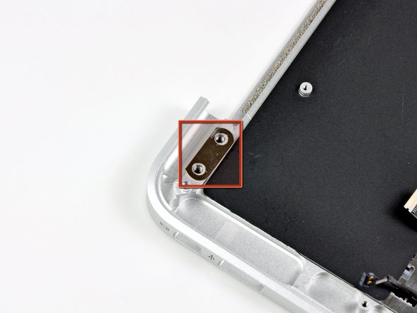
Remove the small rubber gasket from the corner of the upper case near the display data cable.
-
-
Dieser Schritt ist noch nicht übersetzt. Hilf mit, ihn zu übersetzen!
-
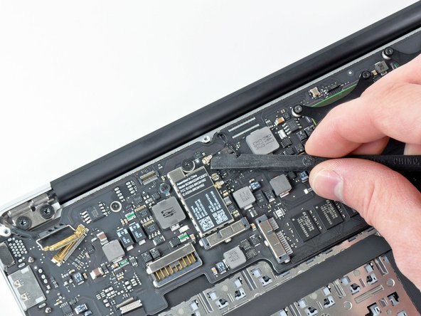
Use the flat end of a spudger to pry both antenna cable connectors up and off their sockets on the AirPort/Bluetooth card.
-
-
Dieser Schritt ist noch nicht übersetzt. Hilf mit, ihn zu übersetzen!
-
Gently de-route the antenna cables from the slot cut into the logic board.
-
-
Dieser Schritt ist noch nicht übersetzt. Hilf mit, ihn zu übersetzen!
-
Remove the three 3.6 mm T5 Torx screws securing the logic board to the upper case.
-
-
Dieser Schritt ist noch nicht übersetzt. Hilf mit, ihn zu übersetzen!
-
Gently lift the logic board assembly out of the upper case, minding the fragile heat sink and any cables that may get caught.
-
-
Dieser Schritt ist noch nicht übersetzt. Hilf mit, ihn zu übersetzen!
-
Pull the camera cable parallel to the face of the I/O board toward the rear edge of the Air to disconnect it from its socket.
-
-
Dieser Schritt ist noch nicht übersetzt. Hilf mit, ihn zu übersetzen!
-
Remove the small rubber gasket from the corner of the upper case nearest the I/O board.
-
-
Dieser Schritt ist noch nicht übersetzt. Hilf mit, ihn zu übersetzen!
-
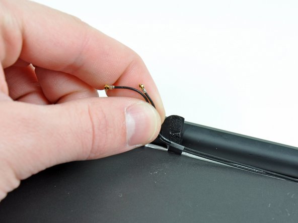
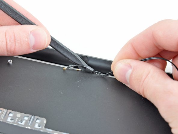
Peel up the six cable loops securing the antenna cables to the upper case.
-
Gently pull the cable loops slightly out of the channel cut into the upper case one at a time.
-
Use your spudger to open up the plastic loops as you de-route the antenna cables through them.
-
Repeat this for all five retaining loops.
-
-
Dieser Schritt ist noch nicht übersetzt. Hilf mit, ihn zu übersetzen!
-
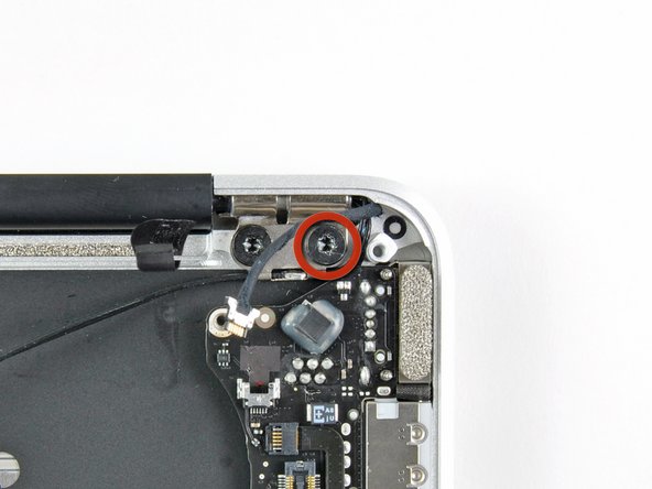
Remove the outer 4.9 mm T8 Torx screw securing each display hinge to the upper case (two screws total).
-
-
Dieser Schritt ist noch nicht übersetzt. Hilf mit, ihn zu übersetzen!
-
Open the display until it is perpendicular to the upper case and place it on a table as shown.
-
While holding the Air steady, remove the remaining 4.9 mm T8 Torx screw from the lower display bracket.
-
-
Dieser Schritt ist noch nicht übersetzt. Hilf mit, ihn zu übersetzen!
-
Remove the last 4.9 mm T8 Torx screw securing the display to the upper case.
-
-
Dieser Schritt ist noch nicht übersetzt. Hilf mit, ihn zu übersetzen!
-
Push the upper case slightly toward the display assembly, then rotate it away from the front of the display assembly.
-
Once the two display hinges have cleared the upper case, remove the display and set it aside.
-
-
Dieser Schritt ist noch nicht übersetzt. Hilf mit, ihn zu übersetzen!
-
Use the flat end of a spudger to pry the right speaker off the adhesive securing it to the upper case.
-
Remove the right speaker from the upper case.
-
-
Dieser Schritt ist noch nicht übersetzt. Hilf mit, ihn zu übersetzen!
-
Use the tip of a spudger to carefully flip up the retaining flap on the microphone cable ZIF socket.
-
Pull the microphone ribbon cable straight out of its socket.
-
-
Dieser Schritt ist noch nicht übersetzt. Hilf mit, ihn zu übersetzen!
-
Use the flat end of a spudger to pry the left speaker cable connector up and out of its socket on the I/O board.
-
De-route the left speaker cable from the notch cut into the I/O board.
-
-
Dieser Schritt ist noch nicht übersetzt. Hilf mit, ihn zu übersetzen!
-
Remove the single 3.6 mm T5 Torx screw securing the I/O board to the upper case.
-
-
Dieser Schritt ist noch nicht übersetzt. Hilf mit, ihn zu übersetzen!
-
Carefully lift the I/O board from its edge nearest the logic board and remove it from the upper case.
-
-
Dieser Schritt ist noch nicht übersetzt. Hilf mit, ihn zu übersetzen!
-
Use the flat end of a spudger to pry the left speaker off the adhesive securing it to the upper case.
-
Remove the left speaker from the upper case.
-
-
Dieser Schritt ist noch nicht übersetzt. Hilf mit, ihn zu übersetzen!
-
Use the tip of a spudger to pry the microphone away from the side of the upper case.
-
Remove the microphone from the upper case.
-
Upper case remains.
-
-
Dieser Schritt ist noch nicht übersetzt. Hilf mit, ihn zu übersetzen!
-
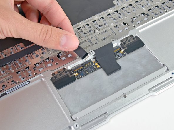
Use the tip of a spudger to pry up the retaining flap on the trackpad data cable ZIF connector.
-
Gently slide the trackpad ribbon cable out of the ZIF connector.
-
-
Dieser Schritt ist noch nicht übersetzt. Hilf mit, ihn zu übersetzen!
-
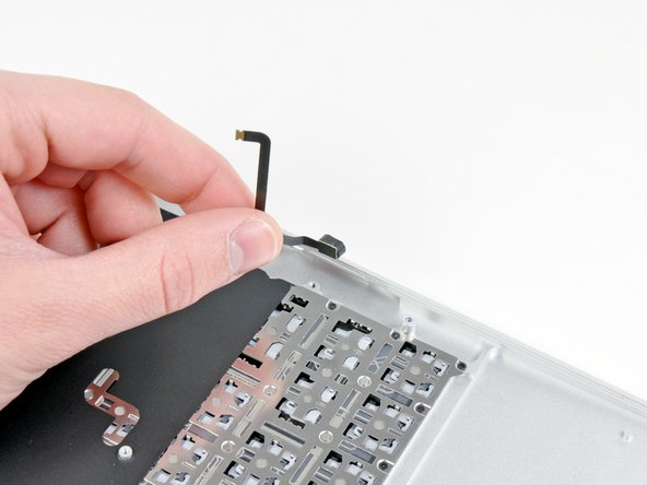
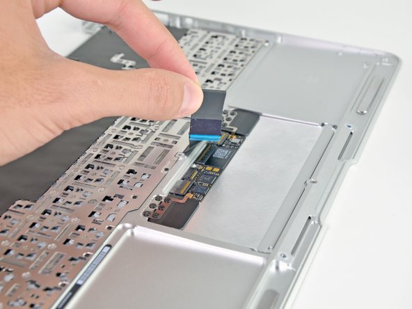
With one hand, lift the keyboard ribbon cable up and push it slightly away from the trackpad to access the ZIF connector underneath.
-
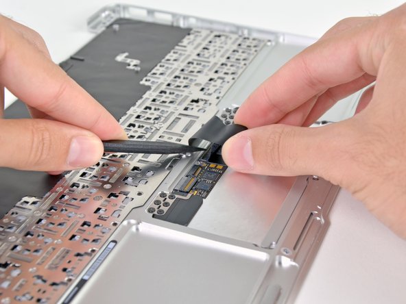
Use a spudger tip to pry up the retaining flap on the keyboard ribbon cable ZIF connector.
-
Gently slide the keyboard ribbon cable out of the ZIF connector.
-
-
Dieser Schritt ist noch nicht übersetzt. Hilf mit, ihn zu übersetzen!
-
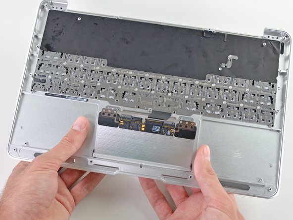
Remove the six 1.5 mm Phillips #00 screws that secure the trackpad assembly to the upper case.
-
-
Dieser Schritt ist noch nicht übersetzt. Hilf mit, ihn zu übersetzen!
-
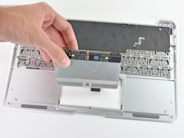
While supporting the upper case, press up on the side of the trackpad closest to the logic board.
-
Remove the trackpad.
-


Rückgängig: Ich habe diese Anleitung nicht absolviert.
28 weitere Nutzer:innen haben diese Anleitung absolviert.


3 Kommentare
There is a T5 screw-thing in the upper case below the track pad. Adjusting this changes the play in the track pad 'click', though be careful since nothing stops it from being screwed too far in. It's not mentioned in the guide, but if you're replacing the upper case you will want to make sure the screw is installed and adjusted to your clicking taste!
netherby makes a good point about the tension screw for the trackpad!
This is a funny headless screw which goes in between the trackpad and the edge of the upper case. I pulled the trackpad from the old case without noticing this, reassembled to find the trackpad all weirdly loose. Tension screw fixed it.
The hard case is great for putting in my backpack and not worrying about the computer getting damaged. http://bestapplecases.com/best-macbook-a...