Einleitung
Kein Saft mehr? Tausche die MagSafe-Platine.
Was du brauchst
-
-
Löse die acht 4 mm Kreuzschlitz Schrauben, die die untere Abdeckung befestigen.
-
-
-
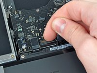
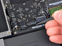
Hebe die untere Abdeckung vorsichtig in der Nähe der Lüftungsöffnung an.
-
Öffne den Spalt weiter mit den Fingern, bis sich die Abdeckung von den verbleibenden Clips löst.
Do the retaining clips have to be re-engaged when replacing the lower case?
Answering my own question, the clips re-engage when the lower case is correctly positioned. You can help them by gently pressing the lower case with your thumbs midway along the two short sides. When everything is correctly aligned the eight screw holes line up.
Rather than running your fingernail down the sides to free up the retaining clips, I found that using an old credit card, inserted about 1/4”, to run along the left and right side popped those end retaining clips right off with no problem. You may need to twist the card slightly when in the middle area to help pop those off.
-
-
-
Hebe den Akkuanschluss mit dem flachen Ende des Spudgers aus seinem Sockel auf dem Logic Board.
you do not need to remove the battery when replacing the hard drive or ram
Be careful of the corner of the battery cable connector when trying to pry it off with the spudge. I knocked the corner of mine. No operational impact but was not very pleasing!
Not necessary, but a good idea, so as to avoid any spurious charges going through the boards...
@Svenaustx - What could happen if not removing this battery? Worst case? Not a geek on this but did change RAM on my Macbook Pro "15. Can't remember disconneting the battery back then. Shouldn't it be sufficient shutting the Mac off and ensure it has been used for an hour or so before replacing RAM?
-
-
-
Entferne die folgenden Schrauben auf der Seite mit dem optischen Laufwerk am hinteren Lüftungsgitter:
-
Zwei 10 mm Torx T8 Schrauben
-
Zwei 5,2 mm Kreuzschlitzschrauben
I have a problem with the two middle screws
same here...
-
-
-
Entferne folgende Schrauben von der Seite mit den Anschlüssen am hinteren Lüftungsgitter:
-
Zwei 10 mm Torx T8 Schrauben
-
Zwei 5,2 mm Kreuzschlitzschrauben
-
-
-
Hebe vorsichtig das hintere Lüftungsgitter aus dem oberen Gehäuse.
you can actually stop disassembling now and try to replace it now. after removing two t6 screws it came off pretty easily
Good tip, thanks! I skipped ahead to step 17 and had no problem getting the magsafe board out from under the logic board and the new one installed. Saves a lot of work disconnecting connectors indicated as Fragile!
matt15 -
Thank You! Saved me an hour or so of work and a lot of stress!
I also did Step 6, then skipped to Step 17 & 18. Once I had the display data cable off, I could remove the 2 T6 Torx screws holding the MagSafe board on and remove it. You can reach under the logic board with the point of the spudger to work the cable out of the socket. Note how you maneuver the board out of the tight space so you can maneuver it back in. When you put the new MagSafe board in, plug in the cable first. If you bend the wires so the plug approaches the socket at the appropriate angle, you can nudge it in with the pointed end of the spudger.
Thanks a lot for this hint! You saved my macbook, when I failed to unscrew the fan because of one completely destroyed screw. Thanks to your comment I skipped steps 7-16 and went straight to replacing the magsafe board without problems. The spudger and some 3D imagination and done,
-
-
-
Benutze das flache Ende eines Spudgers, um das AirPort / Bluetooth-Flachbandkabel vom Logic Board abzulösen.
The steps from 7 up to 16, and then 19 and 20 are not necessary. It looks like Apple intentionally designed the shape in the corner around the magsafe connector, so that it can be replaced without disconnecting and unmounting the main board. Also, the placement of the two screws mounting the magsafe board confirms that - they are easily available. This is true at least for the 2009 model, which I've successfully repaired.
So you can skip the risky steps of disconnecting of all the main board connectors and go straight to unscrewing the magsafe connector. Then, having the spudger and some 3D imagination, you can remove the magsafe board with some 3D rotations. Same for mounting the new magsafe.
I've found out that crucial simplification only because I failed to unscrew the fan (broken a screw completely, while following this guide step by step). Then I found a comment from user grze under step 6, which saved my macbook by confirming, that 7 to 16 can be skipped.
-
-
-
-
Heble den Lüfterstecker mit einem Spudger gerade nach oben ab und aus seinem Anschluss auf dem Logic Board heraus.
Since this kind of connector and very fragile and easy to damage even with a spudger I use a needle that I insert in the front side of the connector, between the connector and the socket and only apply a little pressure while lifting up the needle. The connector will then pop up from one side. Repeat the procedure for the other side. With this method it's impossible to damage the connector. I adopted this method after ruining two or three connectors using the spudger.
Hi, how do you fix the axial which connects the fan with logic board..it's broken! Thanks in advance..
HELP! Both the connector AND socket detached from the logic board! Is it possible (barring micro-surgery) to reattach the socket to the logic board?
same problem here...any ideas? Did you fix it again, John?
Ben Kn -
I disconnected the connector and socket from the logic board because I wasn't being careful and wasn't using a spudger tool as was recommended. Luckily, a friend of mine that's handy with a soldering gun was able to individually solder each wire from the cooling fan's wire assembly back onto the soldering points on the logic board. It's really intricate, tricky, and risky...but at that point, what choice do you have? I verify it's possible to fix and my cooling fan is now running perfectly fine.
Hi my name is Lynn I made a mistake on the logic board trying to detach fan from laptop
A1342 and the whole thing came off so I was wondering do
I solder it back on or how can I fix it thank you and be Blessed
-
-
-
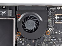
Entferne die folgenden drei Schrauben, mit denen der Lüfter am oberen Gehäuse befestigt ist:
-
Eine 7,1 mm Kreuzschlitzschraube
-
Zwei 5 mm Kreuzschlitzschraube
-
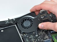
Hebe den Lüfter aus dem oberen Gehäuse.
-
-
-
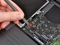
Löse den empfindlichen Stecker des rückwärtigen Lautsprechers vom Logic Board ab. Diese kleinen Stecker des rechten und linken Lautsprechers gehen leicht kaputt.
While these connectors are very delicate, a new upper body case will have new connectors already installed. I slightly broke two connectors while removing them.
Also, the connectors have a notch underneath (on the logic board) for the corner of the spudger to fit into. The hard part is that you cannot see the notches until the connectors are removed.
Hi. Long time ago, I know but.... How did you fix them?
I snapped mine off, can it be soldered back on?
Simon G -
I used pointed tip of one side of the tweezers from the ifixit Home Tech Toolkit. I found this thinner pointed tip better than a spudger for hitting that notch in the socket underneath the connectors. Since this is a metal tool, I pried very gently and I was working on a MacBook with the battery taken out entirely (early on as suggested in the video) and was also using an Anti-Static wrist strap. I found the spudger broke one of the connectors because it's relatively thick plastic, and put too much pressure under the cables before the tip could reach the plastic block of the connector. The pressure under the cable popped the wire contact right through the top of the plastic block connector. (it was OK this connector broke since I didn't need to reuse it--my replacement keyboard/upper case came with its own cables.)
Because the tips of the tweezers are angled, I felt I had better control of the torque I was applying than if I used a jeweler's flathead screwdriver.
Totally agree with the needle solution prying up from the side of the connector. A dentist tool is perfect!
(yes, in 2021 i’m fixing a 2009 macbook! :P)
-
-
-
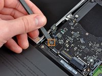
Benutze das flache Ende eines Spudgers, um den Stecker des optischen Laufwerks vom Logic Board abzulösen.
-
-
-
Benutze ein Spudger, um den Stecker des rechten Lautsprechers und den LED-Stecker für den Sleep-Modus vom Logic Board abzulösen.
-
-
-
Benutze das flache Ende eines Spudgers, um den Trackpad-Kabelstecker vom Logic Board abzulösen.
-
-
-
Klappe den Sicherungsbügel am ZIF-Anschluss des Tastatur-Flachbandkabels mit dem Fingernagel hoch.
-
Schiebe das Tastatur-Flachbandkabel mit der Spudgerspitze aus seinem Anschluss.
When reassembling make sure this cable is really deep in it's socket. (Use some force with the spudger wedging it in between the cable and battery). If you don't, you won't be able to power up the board. I had 2 logicboards that I thought were dead, but it turned out the cable was not inserted enough. Jump starting them with the jump pads did nothing (with or without cable connected), but connecting the cable properly made the board come alive. Really check this!!
You sir, just saved my day! Switching boards between two mac and I thought I broke the two at once... This should be documented on the manual!!
Thanks for your help!!! I thought I did the replacement wrong. Greetings from Peru.
This was hugely helpful! The cable requires much more force than expected.
'This should be added to the guide:
There really should be a comment in the steps regarding tips on how to put the ribbon back in. The tape did the trick and I am back up and running.
The two silver squares above the left corner of the Keyboard and to the right of the Trackpad cable ribbon are the jump pads to power on the MacBook if your power button may not be working.
Nope big job to replace it. Use Kapton tape to hold it in place. https://www.amazon.com/Retermit-Resistan...
-
-
-
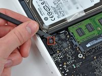
Benutze das flache Ende eines Spudgers, um den Stecker des Festplattenkabels vom Logic Board zu hebeln.
-
-
-
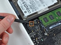
Benutze einen Spudger, um den linken Lautsprecherstecker und den Mikrofonstecker vom Logic Board zu hebeln.
Note: the 2009 and 2010 model differ here. On one the 3 point connector is left and 2 point is right, on the other one the 3 point connector is right and 2 point is left.
I found this while installing several logicboards for A1342.
@Peterdk, are the connectors exchangeable?
I mean, would putting the 3 pin on the 3 pin, and the 2 pin on the 2 pin, regardless of the position (left or right) be ok?
Have you successfully used a 2010 logic board on a 2009 case?
how do you reconnect these?
hi! i know iʻm 6 years late, and you probably figured it out already, but for the rest of us newbies , line the plug over the socket and gently press down. the correct orientation of the plug is the side with the tiny slots in them faces the logic board, aligning with the contacts in the socket. it may help to press the side farthest from the ribbon cable first.
Kahana -
-
-
-
Fasse die Zuglasche aus Kunststoff, die an der Kabelverriegelung des Displays befestigt ist, und drehe sie in Richtung der DC-In-Seite des Computers.
If the video data cable has been disconnected before, the adhesive on the might not hold. Be extra cautious in disconnecting this. An illuminated magnifier would be a good help on this step as it is very delicate. This was where I feared I would fail. Was very relieved in getting through this step...
I wasn't careful enough here, and didn't realize that the silver metal piece around the connector is actually a locking clip. No wonder disconnecting the cable required more than a gentle pull. The clip popped out of the cable-side connector in the process, and was bent; fortunately I was able to very carefully bend the clip out just enough to get it re-seated in the connector; there are tiny slots on the sides of the connector that the clip fits into.
-
-
-
Ziehe den Stecker des Display-Datenkabels vorsichtig aus seinem Anschluss auf dem Logic Board heraus.
-
-
-
Entferne die sechs 4,1 bis 4,4 mm T6 Torx Schrauben, mit denen das Logic Board am Obergehäuse befestigt ist.
-
Entferne die beiden 4,1 bis 4,5 mm T6 Torx Schrauben, mit denen die MagSafe-Platine am Obergehäuse befestigt ist.
-
Bei einigen Modellen können dies Schrauben der Größe T7 sein. Achte darauf, dass du den Kopf nicht mit einem kleineren Bit beschädigst.
-
-
-
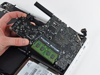
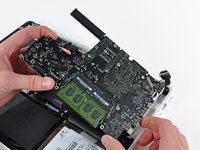
Hebe die Seite des Logic Boards, die den Anschlüssen gegenüberliegt, aus dem oberen Gehäuse heraus.
-
Drehe das Logic Board vom oberen Gehäuse weg, bis die Anschlüsse den Rand des oberen Gehäuses freigeben.
-
Ziehe das Logic Board und die MagSafe-Platine in einem Stück von der Kante des oberen Gehäuses weg.
(When re-installing) Before screwing down the logic board, go around the edge and make sure no cables are caught underneath, remember there are 11 of them, 12 if the battery is present at this point.
I reassembled the macbook A1342 using this guide and everything is perfect, except that if I shut down the computer and power it up after 1hour or so, I have to press the power button a few times before it starts. What could I have gone wrong? I checked the magsafe connector and it seems to be firmly seated. :(
-
-
-
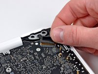
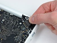
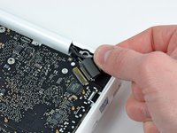
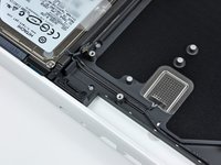
Ziehe den Stecker der MagSafe-Platine aus seinem Anschluss auf dem Logic Board heraus.
-


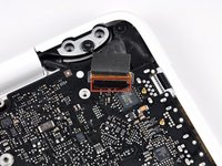


Um dein Gerät wieder zusammenzubauen, folge den Schritten dieser Anleitung in umgekehrter Reihenfolge.
Um dein Gerät wieder zusammenzubauen, folge den Schritten dieser Anleitung in umgekehrter Reihenfolge.
Rückgängig: Ich habe diese Anleitung nicht absolviert.
182 weitere Personen haben diese Anleitung absolviert.
Besonderer Dank geht an diese Übersetzer:innen:
100%

Annika Faelker hilft uns, die Welt in Ordnung zu bringen! Wie kann ich mithelfen?
Hier starten ›

22 Kommentare
I did it Success! Thank you very much!!!!
I had some problems after I reassemble all the parts, first the Macbook wasn't turn on, but I wait few seconds and it's turn on again. Second the key A on the keyboard not worked but I take off the ribbon cable of keyboard and put it on again and the keyboard worked normally.
This is my comment I hope that help someone.
The computer fell on the MagSafe cable, wich pressed in the MagSafe board (socket) into the body so the cable and the socket couldn't reach contact. From this guide I only did steps 1 to 6 and 17 to 19(only the two screws for the MagSafe board). Then I could move the MagCharger board out enough so it could make contact with the charger cable. Then I tightened the two screws again. Allthou I was as carefull I could with the display data cable (step 17 -18) and looked on youtube allso, it did break a bit at the surrounding solder joint. But it's working. I didn't have to replace the MagCharger board, just move it back into position.
Hi I have a problem with the fan connector. I accidentally break the plastic fan socket off the logic board.. I am worried as the way am looking at it its difficult to solder it back as it too tiny.. What should I do?
Hi I have the same problem..any suggestion please!
Same problem! Please help!
Eric -
Well, I wish I would’ve read ALL the comments first. Come to find out I could have avoided breaking the fan contact if I would have just completed to #6 then went to 17 and 18.
Eric -
EXCELENTE!!!
Este guia salvou meu velho macbook. Antes do conserto o conector magsafe "fervia" de queimar os dedos na ponta do carregador. acho que um revestimento desgastado que isolava o magsafe board do conector, fazia ele superaquecer. como ganhei uma sucata de macbook, consegui trocar a peça.
Obrigado IFIXIT!
Agora, tomando coragem para mais um desafio: Trocar todo o corpo externo do meu macbook, pois o atual caiu algumas vezes no chão e está rachado em alguns lugares. pretendo usar a sucata que tenho, pois está melhor que o meu.
Amazing guide.dissasemble until step 6 then skip to 17.saves me a lot of time(approximately 30 min!!!)
use torx 6-8-philips and a pencil.thank you.
Where you guys bought the part?
Thank you for this very helpful guide! I suggest to skip steps 7 up to 16, which is much quicker and safer way, at least for the 2009 model. With that one remark, overall great guide.
Hi , MacBook worked fine but the mag sage silver pins burnt so I had to replace the MagSafe so i did and put it all back to together I plugged the MagSafe in and it turns green then turned orange so I tried turning it on and it just when back to green and to power light didn’t turn on then after a bit of time it turn on and managed to log in thought it was fine but the it just suddenly when off and back to how it was not working can you help ?
Hello Everyone!
I live in Buenos Aires and done plenty of repairs and upgrades to my two Macbooks A1342 at home. But we are on the verge of crisis here. The Magsafe chargers are failing by the minute. At this point I’ve replaced the magnetic cable on one, attached the old one in the new one and switched stuff here and there, but I have two macbooks, one of them with a rotten battery (that changed as new just a few months ago and suddenly, just before the warranty voided, it colpased) and only one charger, which is failing more and more. When I connect it, it blinks the green light nonstop, never changing to orange and not charging the battery.
So, has anyone ever basically “bridged” the magentic socket and welded wires into a regular plug both in the computer magsafe socket AND the charger, in order to leave the magnetic magic behind and sort of Frankenstein the computer in a way that it at least charges?
With This COVID19 Lockdown times there is no way I can use a delivery system to buy parts. HELP!!
MASSIVE PROBLEM HERE!
First things first, thank you so much for such an excellent guide. I replaced the magsafe apparently successfully, since when I plug the charger in, the orange light lights up immediately (first green, then orange).
However, I did break a couple of those delicate sockets as I went through: the fan and the rear speaker ones, and now the computer doesn’t start altogether! I don’t know if it is because of those two broken components or because I screwed up somewhere else during the process, though.
I’ve tried gluing the plastic housings back in place in the hope the pins would actually made contact, but it hasn’t made a change. The computer still doesn’t respond.
Any ideas?
Thanks
notes on my reassembly.
1. the connectors are all on top of the board - then i take the board out, so they are all bent in a tendency that makes them want to go under the board. to reassemble, i had to take care to get them all back in place.
2. the keyboard connector was difficult to get back into the zif connector - i had to take out the battery in order to get it to fit back.
3. the magsafe has oversized holes when screwing them down - it is possible to reassemble so that the magsafe connector is shifted so far forward that the computer side connector will not engage with the charger connector. it is possible to loosen the screws after reassembly by moving the lcd connector, attaching the charger, and retightening, then replugging the lcd.
Note 2 - Another interesting tangential note about this repair is there seems to be a situation with dodgy connectors on the internet marketplaces. The repair guide is excellent and everything works, but my own personal charger-brick side aftermarket connector is glitching out on occasion if not plugged in precisely in the right position. Once it even started ringing at high frequency and got rather hot. I’m not sure if its used connectors with mechanical wear or if its sub-standard parts on the secondary markets or what.
update 3. my replacement board got ‘zapped’ when the magsafe connector was at a weird angle and shorted. At this point i think it was the age and/or wear and tear and/or non-OEM nature of the magsafe connector coming off my wall-wart and also the cheap used replacement board i got. I replaced the power mini-board with a newer one and the magsafe connector on the wall-wart with a newer one, and everything seems OK so far. It is true you can skip most of these steps and just unplug the video connector and gingerly slide out the magsafe board, but its a bit tricky and im glad i went through the whole thing.
According to this page http://support.apple.com/kb/HT1651?viewl..., the 8 screws are not identical.
Can anybody tell me where each kind of screw is supposed to go?
Gregoire - Antwort
They are all 100% Identical. You were probably looking at a different model, or Apple has entered the wrong information... Hey, It happens...
Owen Davies -
The screws on the Late 2009 are identical. The blue lock compound might make tightening some require a little more effort.
svenaustx - Antwort
Can I replace it with a SATA 3 cable?
nm - Antwort
A1342 macbook does not have the right controller to support sata III
Owen Davies -
hi, i just got back from the apple store and they are really keen for me to upgrade to a new laptop since my battery is old and the screen is cracked, so glad i found ifixit i would love to upgrade this puppy! gonna make it a real sleeper! styler hall wrote about sticking 16 gb of ram in his a 1342 ? is this a simply mather of ordering 3 4gb sticks ?aslo i currently have 4 gb and would like to upgrade to 8 ( or indeed 16) does that mean i need to buy all new sticks or can i continue to use the old one and stick a new one next to it ?
thanks again mick van aar, perth western aus.
michelvanaar - Antwort
The A1342 will take up to 16 GB of RAM, however, there are only two RAM slots, so use two 8-GB RAM modules. Other World Computing (OWC) is a great reference source for info on exactly which RAM to use with which model; prices are usually much better on EBay though. Add an SSD from OWC and your machine will really scream!
I hope that helps!
gdesbrisay -
Gregoire is right. The 8 screws are absolutely NOT identical, I’m looking at them right now, weeowey weeowey.
John Guzman - Antwort
I just wanted to say that, in 2020, i used these instructions to replace the magsafe socket on my A1286, mid-2012, pre-Retina MacBook Pro. The internal layout is not quite the same but close enough for me to do the job. I skipped the steps of fully disconnecting the fans and speakers because of what others had said about breaking the sockets. it just meant I had to be extremely careful when lifting up the main board so that I did not tear and break the connections. I was able to disconnect the old magsafe socket with the board flat and in situ, but there was no where near enough room to be able to aline and press home the new par home. Reluctantly i had to lever up the board. This was difficult as there is a tapped post that holds a screw in the way close to where the USB sockets are, that prevented the board lifting up and out. I had to be quite forceful to manouevre the sockets out from the edge of the case.
Paul Burridge - Antwort