Diese Version enthält möglicherweise inkorrekte Änderungen. Wechsle zur letzten geprüften Version.
Was du brauchst
-
-
Entferne die beiden Kreuzschlitzschrauben, mit denen die Abdeckung des Akkus am Gehäuseunterteil befestigt ist.
-
Hebe die Abdeckung an und entferne sie vom Gehäuseunterteil.
-
-
-
Nimm einen Spudger (oder deinen Fingernagel) und hebe den Akku oben an.
-
Fasse den Akku und hebe ihn aus dem DSi heraus.
-
-
-
Zwei Schrauben befinden sich unter den beiden Gummifüßen (rot markiert).
-
Benutze die Spitze eines Spudger, um die Gummifüße aus dem Gehäuse zu lösen.
-
-
-
Entferne die Schrauben, mit denen das untere Gehäuse am DSi befestigt ist:
-
Sechs 5,2 mm Kreuzschlitzschrauben #00
-
Eine 2,7 mm Kreuzschlitzschraube #00
-
-
-
Setze den Spudger nahe der oberen rechten Ecke des DSi zwischen dem unteren Gehäuseteil und dem Bildschirm ein.
-
Führe den Spudger vorsichtig an der Kante des Außengehäuses entlang, damit eine Öffnung zwischen dem Hauptteil und dem Gehäuse entsteht.
-
Führe den Spudger weiter um das Gehäuse des DSi herum, bis der größte Teil des unteren Gehäuses entfernt wurde.
-
-
-
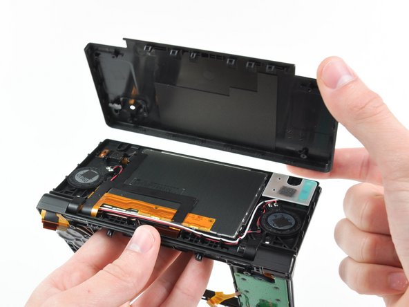
Hebe das untere Gehäuse vorsichtig an der Unterkante an.
-
Löse das Kabel der Lautstärkeregelung und der SD-Karte mit einem Spudger aus dem Anschluss auf der Hauptplatine.
-
Sobald das Kabel vollständig entfernt ist, lässt sich das gesamte Außengehäuse abnehmen.
-
-
-
Ziehe das WLAN-Modul an der Kante, die sich am nächsten zur Kopfhörerbuchse befindet, von der Hauptplatine ab.
-
-
-
Entferne den WLAN-Antennenstecker gerade aus seinem Anschluss auf der WLAN-Platine.
-
-
-
Heble den Stecker der Stromversorgung mit der Spudgerspitze aus seinem Anschluss auf der Hauptplatine heraus.
-
-
-
Klappe die Sicherungsbügel an folgenden drei ZIF-Anschlüssen mit dem Fingernagel oder der Kante eines Öffnungswerkzeugs hoch:
-
Unteres Touchscreenkabel
-
Unteres LCD-Kabel
-
Kabel der Stromversorgung
-
Wenn alle drei Sicherungsbügel geöffnet sind, ziehe die Kabel vorsichtig mit deinen Fingern oder einer Pinzette gerade aus ihren Anschlüssen heraus.
-
-
-
Klappe vorsichtig den Sicherungsbügel am Flachbandkabel zum Touchscreen mit dem Fingernagel oder der Kante eines Öffnungswerkzeugs nach oben.
-
Ziehe das Flachbandkabel zum Touchscreen mit der Spudgerspitze gerade aus seinem Anschluss heraus.
-
-
-
Dieser Schritt ist noch nicht übersetzt. Hilf mit, ihn zu übersetzen!
-
Use your fingernail or the edge of a plastic opening tool to carefully flip up the dual camera ribbon cable retaining flap.
-
Use the tip of a spudger to pull the dual camera ribbon cable straight out of its socket.
-
-
Dieser Schritt ist noch nicht übersetzt. Hilf mit, ihn zu übersetzen!
-
With the tip of a spudger, Pry the microphone antenna up off its socket on the motherboard.
-
-
Dieser Schritt ist noch nicht übersetzt. Hilf mit, ihn zu übersetzen!
-
Remove the following four Phillips screws securing the motherboard to the DSi framework.
-
Three longer screws.
-
One short screw.
-
Pull the microphone and Wi-Fi antenna cables out of the notch cut into the motherboard near the headphone jack.
-
-
Dieser Schritt ist noch nicht übersetzt. Hilf mit, ihn zu übersetzen!
-
Slightly lift the motherboard upwards to reveal the upper LCD ribbon cable above the ABXY buttons .
-
Use your fingernail or the edge of a plastic opening tool to carefully flip up the upper LCD ribbon cable retaining flap.
-
Remove the motherboard from the DSi.
-
-
Dieser Schritt ist noch nicht übersetzt. Hilf mit, ihn zu übersetzen!
-
Use the tip of a spudger to pry the metal backing of the lower LCD up from the DSi's framework.
-
Lift the lower LCD assembly out of the DSi.
-
-
Dieser Schritt ist noch nicht übersetzt. Hilf mit, ihn zu übersetzen!
-
Use a pushpin to remove the four plastic screw covers on the front bezel.
-
-
Dieser Schritt ist noch nicht übersetzt. Hilf mit, ihn zu übersetzen!
-
Remove the four Phillips screws securing the rear bezel to the front bezel.
-
-
Dieser Schritt ist noch nicht übersetzt. Hilf mit, ihn zu übersetzen!
-
Using two hands, gently slide the rear bezel upwards.
-
Slightly close the case of the DSi and lift the rear bezel straight up out of the DSi.
-
-
Dieser Schritt ist noch nicht übersetzt. Hilf mit, ihn zu übersetzen!
-
Continue de-routing the microphone and Wi-Fi antenna cables through the opening located on the bottom DSi's framework.
-
-
Dieser Schritt ist noch nicht übersetzt. Hilf mit, ihn zu übersetzen!
-
Remove the five Phillips screws securing the power board to the DSi's framework.
-
Lift and remove the power board from the DSi.
-
-
Dieser Schritt ist noch nicht übersetzt. Hilf mit, ihn zu übersetzen!
-
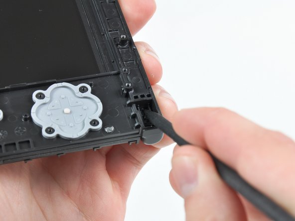
Push the metal hinge pin inward on the D-pad side of the front lower panel with the tip of a spudger.
-
The pin should move about 3 mm and stop. It is not necessary to try to completely remove the pin.
-
-
Dieser Schritt ist noch nicht übersetzt. Hilf mit, ihn zu übersetzen!
-
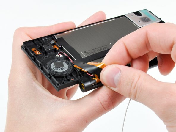
Slightly detach the lower and upper halves of the DSi.
-
De-route the upper LCD and dual camera ribbon cables through the slit near the ABXY side of the front lower panel.
-
Separate the lower and upper halves from each other.
-
-
Dieser Schritt ist noch nicht übersetzt. Hilf mit, ihn zu übersetzen!
-
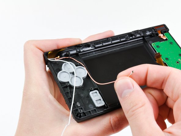
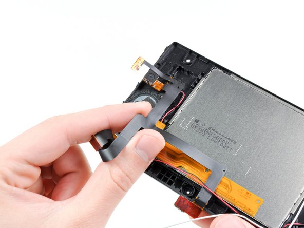
Using your fingers, grasp the microphone cable and de-route it through the hinge.
-
The microphone will likely pop out of its housing, so it is probably easier to completely remove it at this point.
-
De-route the Wi-Fi cable through the hinge.
-
-
Dieser Schritt ist noch nicht übersetzt. Hilf mit, ihn zu übersetzen!
-
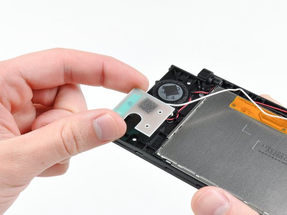
Tightly coil the display and dual camera ribbon cables enough to push them through the steel hinge tube.
-
Remove the steel hinge tube.
-
Carefully push both coiled ribbon cables through the tube molded into the front upper panel.
-
-
Dieser Schritt ist noch nicht übersetzt. Hilf mit, ihn zu übersetzen!
-
Pry the front-facing camera straight up out of its housing in the front bezel.
-
-
Dieser Schritt ist noch nicht übersetzt. Hilf mit, ihn zu übersetzen!
-
Lift the rear-facing camera out of its housing in the front bezel.
-
Remove the dual camera cable assembly from the DSi.
-
-
Dieser Schritt ist noch nicht übersetzt. Hilf mit, ihn zu übersetzen!
-
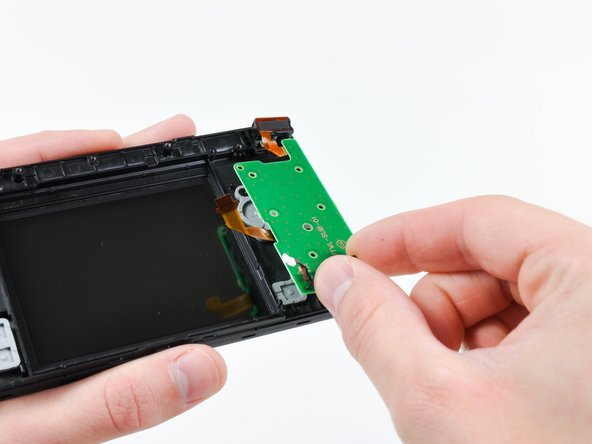
De-route the Wi-Fi antenna cable from its channel in the front bezel.
-
Lift the Wi-Fi antenna board straight up and remove it from the DSi.
-
-
Dieser Schritt ist noch nicht übersetzt. Hilf mit, ihn zu übersetzen!
-
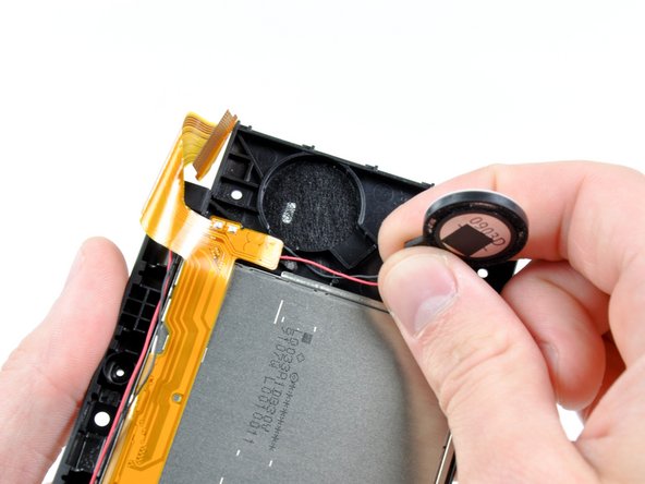
Use the flat end of a spudger to pry the right speaker straight up and out of its housing in the front upper panel.
-
Lift the right speaker and set it on top of the upper LCD.
-
-
Dieser Schritt ist noch nicht übersetzt. Hilf mit, ihn zu übersetzen!
-
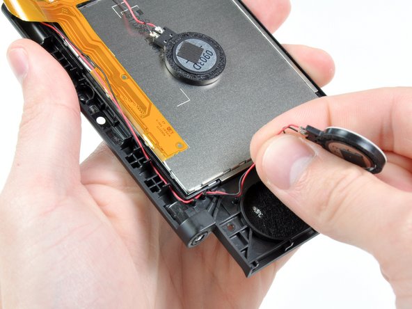
In the same manner as previously described, remove the left speaker.
-
De-route the left speaker cables from underneath the upper LCD.
-
Lay the left speaker on top of the upper LCD.
-
-
Dieser Schritt ist noch nicht übersetzt. Hilf mit, ihn zu übersetzen!
-
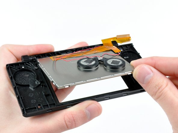
Cautiously wedge the flat end of spudger underneath the upper LCD.
-
Loosen the adhesive by running the spudger along the perimeter of the upper LCD.
-
Lift the upper LCD by its upper right corner and remove it from the front upper panel.
-
-
Dieser Schritt ist noch nicht übersetzt. Hilf mit, ihn zu übersetzen!
-
Desolder the speakers from the upper LCD by heating up the solder joints with a soldering iron and simultaneously using a pair of tweezers to pull the speaker wires away from the logic board.
-


Rückgängig: Ich habe diese Anleitung nicht absolviert.
30 weitere Nutzer:innen haben diese Anleitung absolviert.

12 Kommentare
The tricky part is getting the upper screen and black ribbon through the hinge. I found that curling them and pushing them through a drinking straw that was cut short first and then pushing the straw through the hinge hole made it a whole lot easier.
So true. I just broke my second ribbon cable while replacing the case. While most repairs on the dsi are relatively easy, this ribbon cable makes any repairs that involve it a nightmare.
I curled the larger (new) cable the same way the smaller one was already curled. Just spend some time doing that until it was shaped that way and it was a lot easier to get both through the molded tube and ring.
Tplan -
While doing this I accident messed something up. When I power on the DSi, the bottom screen just flashes and the DS turns off. What did I do wrong?