Einleitung
Der IC im Innern der Lampe scheint einen langsamen Tod zu sterben, der zu flackerndem oder blinkendem Licht führen kann, wenn das Radio verwendet wird. Ebenfalls kann es sein, dass die Tasten nicht mehr korrekt funktionieren.
Das Problem tritt besonders dann auf, wenn das Gerät kalt und/oder feucht ist. Bei Erwärmung des ICs ist die korrekte Funktion wieder hergestellt.
Was du brauchst
-
-
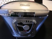
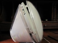
Unter dem glänzenden UL-Aufkleber befindet sich eine Schraube. Entferne den Aufkleber oder schneide ihn ein und entferne die Schraube, um diese Bodenplatte abzulösen.
-
Es gibt zwei Laschen, die das Panel auf der Rückseite der Uhr/des Lichts halten. Wenn es nicht leicht abgeht, musst du mit einem Spudger oder einem Flachschraubendreher am Panel nahe bei der Schraube nach vorne und außen wackeln.
-
-
In diesem Schritt verwendetes Werkzeug:Jimmy$7.95
-
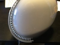
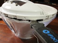
Lege die lamtauf Rückseite, dann wird ein kleiner Abschnitt der Blende sichtbar, der nach oben gehebelt werden kann. Es ist ein kleiner Plastikstreifen mit Haken, die gelöst werden müssen, um sie zu entfernen.
-
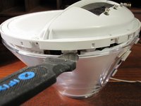
Schiebe die Klinge eines Jimmys direkt in die Spalte über der Abdeckung. Wenn sie sich einige Millimeter geöffnet hat, kippe sie und hebe sie leicht an.
-
Schiebe den Jimmy nach rechts und drücke ihn gegen den Riegel, bis er sich löst. Wiederhole auf der linken Seite.
Getting this section off/out without damaging it is nearly impossible. It’s hooked under the rear rim and it is held down by three clips. I ended up cutting the little bows that connect it to the back and then used pliers on one side to, well, basically break it out…
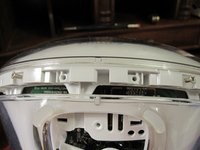
This stage was tricky but by poking a small flat-head screwdriver in alongside the tabs shown in the photo and twisting, I was able to remove it in one piece. Careful studying of of the image above shows where you need to go. Thanks for this excellent guide, I would never have figured this out without it.
Use a plastic tool or a something like a credit card to get that part out: it won’t break it and it is actually quite easy to remove (same tool used for smartphone)
Wow, this would have been impossible to do without seeing the pic of the part! I managed to get it free using a tiny flat-head screwdriver to the clip (all three, one by one) and a larger one pushing up on the rim simultaneously.
Thanks also from my side, it would have been an impossible mission without your guide and excellent illustrations. I also succeeded to remove the plastic strip lock with a tiny flat-head screwdriver and a pair of good steel pliers. No damage.
My model had a screw instead of the clips and was easy to remove. I did use a plastic pryer and think that helped.
-
-
-
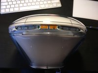
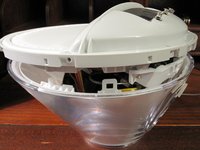
Wir können endlich zwei weitere Kreuzschlitzschrauben lösen, um den Knopfring zu entfernen.
-
Tipp: Hebe den Ring an einem Ende hoch, wobei du ihn zur Rückseite des Weckers hin kippst. Dadurch lösen sich die Haken unter der rückseitigen Rille und du kannst ihn weiter ablösen.
Lift one end of the ring, tilting it toward the back of the alarm clock. That will get the bows out from under the rear rim so you can start removing it..
-
-
-
-
Nun müssen die sechs Schrauben entfernt werden, die die vordere Abdeckung festhalten. Dann kann die vordere Abdeckung nach vorne abgezogen werden.
-
-
-
Entferne die vier Schrauben, mit denen die innere Streuscheibe befestigt ist.
-
-
-
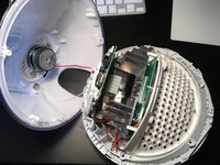
Die innere Lichteinheit wird von zwei Laschen unten links und an der rechten Seite gehalten.
-
Nimm ein Metallwerkzeug mit dünner stumpfer Klinge, z.B. einen Jimmy und drücke die hintere Lasche nach innen, bis sie sich löst.
Wooaw, that was scary but I did it. It really seems that there are additional screws to remove near the tabs, but really it's not the case. There ARE screws, but they don't need to be removed (and they face inwards anyway so they couldn't be removed).
-
-
-
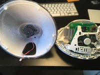
Trenne den Lautsprecher von der Hauptplatine ab.
-
Löse die Schraube und die Unterlegscheibe auf der Rückseite beim Lautsprecher und hole den Antennendraht darunter heraus. Ziehe die Antenne ganz durch, so dass die Rückseite entfernt werden kann.
-
-
-
Ersetze auf der Hauptplatine mit der Strombuchse den MXT2410-Schaltregler-IC (SO-8-Gehäuse).
-
Bei eBay.com ist der Chip zur Zeit beim Händler "adeleparts2010" verfügbar, das kann sich natürlich jederzeit ändern.Ursprünglich würde auch der Pin kompatible Quorvo (ACT4060ASH-T) empfohlen, es hat sich aber herausgestellt, dass er nicht geeignet ist und eher weiteren Schaden verursacht.
Bonjour, je l'ai acheté pour 2€ ici : https://fr.aliexpress.com/item/100500563...
Broffrey -
I always bought from this seller:
https://www.ebay.de/str/adeleparts2010
Very good and fast.Note to the marked resistors:
I initially could not find MXT chip, and thought I was smart and replace with an ACT4060 from Corvo, but that was not stable and blew up on me. For that wrong fix, I had to modify the feedback resistor divider. That is NOT necessary when just replacing MXT2410.
Sorry !
Hi @goaty , can you comment on the suggestion from @fex42 about using an MP1584EN chip? On paper, it looks to be a better chip with higher max ratings (3 vs 2 A, 1.5 vs 1 MHz, 28 vs 20 V). fex42 also said piggybacking the chip was simpler than removing the old one, but they were vague about how it got wired up. I cannot find the MXT2410SX datasheet so I do not know if this is supposed to be a pin-compatible replacement.
On Dec 8, 2024 @fex42 wrote:
Instead of repairing the defective 5V control circuit, I simply piggybacked a small switching regulator on top with thick double-sided tape. By removing the coil, the output of the defective original regulator is separated from the rest of the circuit and you have a nice contact on the board to feed in the 5V. This is not only much easier than replacing the chip (which I also have done successfully some years ago) but these small DC-DC buck converters with MP1584EN chip are simpler to source than the original MXT2410SX chip and also cheap.
hackerb9 -
-


Folge diesen Schritten in umgekehrter Reihenfolge, um dein Gerät wieder zusammenzubauen.
Folge diesen Schritten in umgekehrter Reihenfolge, um dein Gerät wieder zusammenzubauen.
Rückgängig: Ich habe diese Anleitung nicht absolviert.
23 weitere Personen haben diese Anleitung absolviert.
Besonderer Dank geht an diese Übersetzer:innen:
100%


Diese Übersetzer:innen helfen uns, die Welt zu reparieren! Wie kann ich mithelfen?
Hier starten ›
Team

41 Kommentare
Hi Thomas,
I have the same problem, but i do not understand what you are doing with the R3 and R4. If i remove R4, with what should i replace it?
Or how should i measure it?
Thanks in advance,
Arnoud
I can only do it in Germany
Hallo Thomas,
ich finde das ist eine tolle Anleitung zur Reparatur des Lichtweckers. Ich hatte mich auch auf den Austausch des MXT2410 konzentriet. Es kam dann aber doch anders. Nach ca. 2-3 Wochen warten auf den ACT4060 war dieser schnell eingebaut. Das Ergebnis war enttäuschend. Keine Änderung, die 5V waren nicht messbar. Bei der weiteren Fehlersuche stellte ich fest, dass der ACT4060 und die zugehörige Drossel schnell warm wurden. Jetzt ging es an die Suche nach einem Kurzschlußkandidaten. Er war dann schnell gefunden: D3 (SK24). Eine andere Schottkydiode eingebaut (diesmal aus der Bastelkiste) und es wurde wieder Licht und Musik.
Freundliche Grüße,
Roland
Thanks for the feedback. I wasn´t 100% sure the ACT4060 can work correctly. Your feedback has confirmed it will work.
Did you make a modification to the resistors ? Did you measure the voltage ?
Hallo Roland,
vielen Dank für den Tipp mit der Schottky-Diode!
Bei mir war es nur diese Diode, die defekt war.
Nach dem Tausch läuft der Wecker wieder!
Viele Grüße
Andreas
hebel23 -
I was able to use this guide to bring a Philips Wake-Up HF3520 back from the dead. Was able to source a MXT2410SX IC via ebay (5 for $10.23), so just swapped the IC and did not touch the resistors. Thank you OP for identifying the failing component.
Hallo Thomas,
mein HF3520 spinnt auch, wenn es kalt ist. Ich habe selber keine Ahnung von Elektrotechnik. Hättest du Interesse und Zeit ihn zu reperarieren. Ich wohne in München Oberföhring.
Viele Grüße
Mathias
Hier gibts keine Privatnachricht, leider. Bitte eMail an ifixit@e-mail.de
Sicher kann ich es probieren, allerdings hab ich nur den Alternativchip hier noch irgendwo, der MXT müßte erst bestellt werden.
Alles ohne Garantie ;-)
Kannst es schicken oder vorbeibringen. Westendstraße nähe OBI. Genaueres müßte ich eine PM schreiben.
Hallo Thomas,
ja die Widerstände mussten etwas angepasst werden. Auf der Platine ist Platz für einen kleinen SMD-Trimmer.
Das machte die Sache etwas einfacher. Mit Hilfe des Datenblattes und Kontrollmesungen der Spannung war die Einstellung kein Problem.
Nochmals Danke für deine tolle Anleitung,
Viele Grüße Roland
Worked for the second time with the ACT4060 and adapted resistors. However, this IC is actually specified only up to 20V, I saw afterwards. That could explain your blow-up, Thomas.
Once the external 24V power supply was also broken. I replaced it with a 12V power supply I had left over from an external hard drive.Seems to work fine and also protects the ACT4060 :-)
The power source must be 17V - 24V. If power is lower than 17V the light on maximum is yellow instead white. What i do. I replaced IC1 with ACT4060, added 1K resistor for R3+R4, and added 12V DC-DC for ACT4060. Remove L5, get 24V from one pin to DCDC in and connect second pin L5 to DCDC 12V out. I think this construction must work longer. For DCDC i use MP1584 module that i found in my parts box, i think also LM7812, LM7809 is suitable
And yes its still working without any problems
The strain in the middle besides the coil and the capacitor is just glue to keep the cable in place.
Look for other damage like blown up capacitor.
Thank you so much Thomas @goaty for this detailed Fixit !
Eventhough i have experience in electronics i would never thought about the power IC for this behaviour.
II've replaced the IC with the MXT2410SX that you can find on ebay here : "https://www.ebay.com/itm/393179218389" the lamp and all it's fonctionnalities is perfect since then ! I did that like 6 months ago and it still working perfectly (sorry i've just had time to give my feedback).
Changing the IC is a little bit technic but it still conceivable with some tutos for non experienced persons.
I'm glad to discovre this community thanks to your fixit i'll try to add some of mines as possible.
Vielen Dank für die gute Anleitung!
Wenn bei dem Wecker irgendwelche Tasten nur noch unzuverlässig reagieren, kann man die Gelegenheit nutzen, um die zu reinigen:
- mit einer spitzen Pinzette die das weiße Klebeband vorsichtig abziehen
- Klebeband mit der Pinzette festhalten und mit einer zweiten Pinzette das im Inneren vermutlich dunkel angelaufene Metallplättchen abziehen
- Metallplättchen vorsichtig wieder glänzend polieren (bei mir hat einer der spitzen blauen Poliergummischleifer von Proxxon perfekt dafür funktioniert)
- Plättchen und Kontakt mit Isopropanol reinigen
- Plättchen wieder in seine Aussparung kleben und Klebeband mit Plättchen zurück auf die Leiterplatte kleben, vorsichtig ringsum wieder gut andrücken.
My HF3520 is down.
May I ask a question? I don't know much about converter, but why do you use an ACT 4060 ? The ACT4072 is 1.222V (but do we care?) and support 30V input.
Does it work better?
(by the way, anybody has the mxt2410 fact sheet?, and what does all this numbers mean?)
I thought I was smart by using ACT4060 as replacement of MXT, but it did not work, and blew up on me, so I wrote that it is not good replacement !
Better buy MXT2410 original from China, 10pcs for around 10Dollars, it works perfect.
Thanks! It was the problem in my case as well. I did't want to use new MXT2410 because I suspect that it would die after few years again. Thus, instead of ordering new MXT2410 I just desoldered it, as well as removed the Shottky diode and the inductor, and installed a bypass from a readily available module based on MP1584 (just because I already had one at hand), for example: https://www.tinytronics.nl/shop/en/power...
On eBay there is a seller "adeleparts2010" which is very reliably sending replacement parts from China. No problems had whatsoever.
Vielen Dank Thomas für die tolle Anleitung. Ohne die hätte ich nicht herausgefunden, woran das Problem liegt. (Hab gerade den Test mit dem Fön gemacht, damit geht der Wecker aktuell wieder). Davor haben sich ständig alle Displaytasten von selbst gedrückt.
Ich habe mir auch gerade den MXT bestellt, bin aber selbst kein großer Löt-Künstler. Ich wohne auch in München, könntest du mir evtl. mit dem Problem aushelfen?
Vielen Dank und Grüße
Michael -
Gerne Kontaktaufnahme über ifixit@e-mail.de Gruß Thomas
Hatte ein ähnliches Fehlerbild. HF3520 schaltete sich nach einem Stromausfall nicht mehr ein. Habe daraufhin den unteren Schacht (siehe Schritt 2) entfernt und das Innere ca. 5 Sekunden mit dem Föhn erwärmt. Danach den Stromstecker wieder eingesteckt. Deckel anbringen. Läuft wieder. Keine Reparatur im engeren Sinn aber im Vergleich zur SMD-Löterei sehr minimalinvasiv.
Hello! My HF3520 suddenly cut out in the middle of the alarm and now is non-responsive. When plugged in, there's no display or response to the buttons. I've left it unplugged for a while, and also plugged it in for a while but nothing happening. I can't believe that it's unfixable and I'd really like to fix it or take it to a repair cafe. Has anyone else had a similar issue? I'm trying to work out if it's most likely to be a chip / bulb/ cable issue. Does anyone know what bulb it takes?
Bonjour à toutes et tous,
Je remercie chaleureusement le créateur et les contributeurs de ce post car j'ai pu réparer mon réveil grâce à vous.
Pour cela, j'ai acheté cette pièce HWD SOP-8 MXT2410SX 2410 sur un grand site marchand chinois connu, et n'ai pas eu besoin de toucher aux résistances.
La manipulation a été difficile et longue pour moi (je suis débutant en soudure).
A plus.
Olivier
Bei mir war auch 5V ausgefallen, stattdessen 0,4V. Wenn man 5V zuführt, so startete der MXT2410 und es funktionierte ohne externe 5V. Ich habe einen Linearregler LM7805 TO220 zusätzlich eingelötet, nun funktioniert es. Der Oszillograf zeigte keinen Defekt des Elkos am Ausgang an. Der LM7805 macht hier 4,99V. Der MXT2410 macht 5,15V, d.h. im Betrieb übernimmt der MXT2410. Wenn er total ausfällt, kann der LM7805 übernehmen. Allerdings steigt der Stromverbrauch und die Wärmeproduktion um 400mW(?); in diesem Fall würde ein SOT32-Gehäuse überlastet.
Im Datenblatt des ACT4060 ist ein enable-Pin, das intern mit 2µA aktiviert wird. Wenn dieses offen ist, dann könnte der Regler nicht aktiviert werden wenn 2µA nicht reichen. Das erklärt das thermische Verhalten eventuell.
Hallo Zusammen,
Ich habe 2 Philips HF 3520. Einer der beiden läuft wunderbar, der andere leider nicht. Der "Sonnenaufgang" startet wie er soll. Sobald jedoch das Weckgeräusch startet fängt das Licht an "aufzublitze" und zu flackern.
Kann mir hier Jemand helfen an welchem Bauteil es in diesem Fall liegen könnte?
Ich freue mich über Hilfe, da ich den Wecker ungern entsorgen möchte.
Hallo, es ist auch mit 99% Warscheinlichkeit der defekte 5V-Schaltregler-Chip MXT2410. Sag bescheid, wenn du einen Chip brauchst oder Hilfe beim Löten. ->ifixit@e-mail.de
it was not easy to replace the MXT2410SX but it seems to have fixed my wake up light :).
thanks for the information.
Instead of repairing the defective 5V control circuit, I simply piggybacked a small switching regulator on top with thick double-sided tape. By removing the coil, the output of the defective original regulator is separated from the rest of the circuit and you have a nice contact on the board to feed in the 5V. This is not only much easier than replacing the chip (which I also have done successfully some years ago) but these small DC-DC buck converters with MP1584EN chip are simpler to source than the original MXT2410SX chip and also cheap.
Nice idea, fex42! Did you take photos of the process? It would be good to update the guide with your simpler piggyback method.
''''
I can't find the datasheet for the original MXT2410SX chip, so I'm not even sure what "pin compatible" looks like or why removing the coil disconnects the defective chip. Can you explain a little more?
''''
It looks like Monolithic will be discontinuing the MP1584EN. Would the MP2410GJE or MP2338 work? I notice that the 1584 seems to have much better specs (higher current, voltage, and switching speed), but it'd be good to give people options if it starts becoming hard to find.
hackerb9 -
I don't know much about electronics but I can confirm the solution by fex42 works. I removed the coil marked with 220 and took a very small adjustable step-down buck converter, set it to 5v (usually you use a solder bridge) and soldered wires from the buck converter to points on the PCB labeled with GND and 5v. For the 24v input I poked around with a multimeter and eventually decided to just attach it too the leg of the big capacitor next to the coil. I wasn't 100% sure which other pads too use and this works. Unfortunately I don't have photos, I was too eager to reassemble everything.
joemelon -
My fix works since more than a month now without any problems.
Here are two photos where you can see how my fix is connected and how it fits under the case. Feel free to use that pictures into the instructions (I don't know how to do that):
fex42 -
There is one screw under this tab that's hold the front ring attached in fact. I guess you should have removed it too before prying this ring open
Luuk Akkerman - Antwort
That one does not hold the ring but the cover (step 4).
Wozu das denn -