Diese Übersetzung enthält möglicherweise noch nicht die neuesten Änderungen der Original-Anleitung. Hilf mit, die Übersetzung zu aktualisieren oder sieh dir die Original-Anleitung an.
Einleitung
Diese Anleitung zeigt dir, wie du den Prozessor und die Kühleinheit des PowerMac G5 tauschen kannst. Aufgrund vom Aufbau des PowerMac's ist es schwer den Prozessor zu tauschen, ohne andere Teile auf dem LogicBoard zu beschädigen.
Was du brauchst
-
-
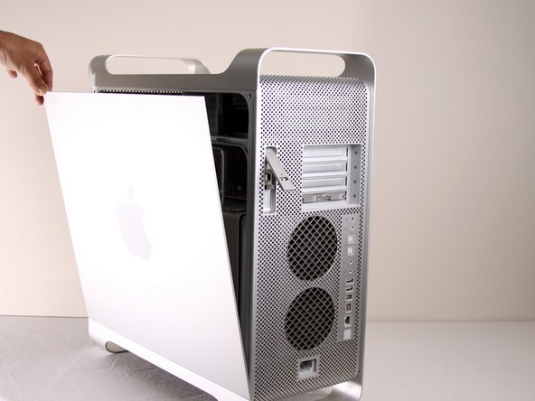
Entferne das Luftleitelement (die durchsichtige Plastikabdeckung) durch Ziehen am Griff.
-
-
-
-
Auf dem Foto ist die Baugruppe rot umrandet (in einem Kasten).
-
-
-
Entferne die G5 Metal Abdeckung vom Computer.
-
Ziehe die Metall-Platte nach links und entferne diese anschließend.
-
-
-
Trenne die Verbindung der Lüfter-Baugruppe vom LogicBoard. Wenn eine Grafikkarte eingebaut ist, dann musst du die Verbindung vorsichtig herunterziehen, zwischen der Grafikkarte und dem LogicBoard
-
-
-
Die Halterung der Lüfter-Baugruppe ist Rot mit den beiden Kästen umrandet.
-
Während du diese runterdrückst, musst du die Lüfter zurück ziehen in Richtung Kühlung.
-
-
-
Nachdem die Baugruppe entfernt ist, müsste es so in etwa wie auf dem Bild aussehen.
-
-
-
Die Kühleinheit des PowerMac G5 ist rot umrandet.
-
Lege den PowerMac so auf den Tisch, das der geöffnete Teil von oben zusehen ist, sodass der PowerMac G5 liegt und nicht normal steht.
-
-
-
Entferne die 8 rot umrandeten T10 Schrauben von der Kühlungseinheit. Die Schrauben sind tatsächlich Inbusschlüssel.
-
Das bevorzugte Werkzeug sind Inbusschlüssel mit langem Griff. T10 hat eine Größe von 2,74 mm (der nächstgelegene Inbusschlüssel hat eine Größe von 2,5 oder 3 mm) und T15 hat eine Größe von 3,27 mm (der nächstgelegene Inbusschlüssel hat eine Größe von 3 mm oder 4 mm). Achte darauf hochwertiges und geeignetes Werkzeug zu verwenden.
-
Die Schrauben kannst du nur loose drehen, allerdings nicht entfernen
-
Die letzen beiden Bilder zeigen die Version des LCS (Liquid Cooling System (Wasserkühlung)) aus einem anderen Computer und aus einem anderen Blickwinkel, um die 8 Schrauben zu zeigen.
-
-
Dieser Schritt ist noch nicht übersetzt. Hilf mit, ihn zu übersetzen!
-
Pull the cooling/processing unit straight up to prevent damage to logic board
-
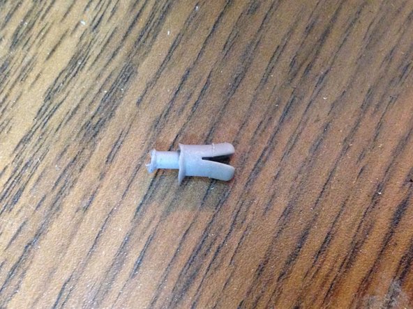
The sleeves around the 6 screws may hold it in, if so just take a pair of needle nose pliers and gently squeeze the sleeves until it releases.
-
Pull the bottom, then side towards the bottom of the CPU case, first to move around the bottom coolant sleeve around the heat sinking bracket. *heat sinking bracket not in picture*
-
-
Dieser Schritt ist noch nicht übersetzt. Hilf mit, ihn zu übersetzen!
-
NOTE: Here are the standoffs without the cooling unit installed to make it easier to understand where the screws are located. Remove the bottom 2 standoffs so it is easier to remove the power supply.
-
Check the pin connections for any damage. All the pins highlighted in yellow should appear straight up and not appear bent. DON'T TOUCH THE PINS. A bent pin will result in your computer not powering on.
-


Um das Gerät wieder zusammen zu bauen, musst du die Anleitung in umgekehrter Reihenfolge befolgen.
Um das Gerät wieder zusammen zu bauen, musst du die Anleitung in umgekehrter Reihenfolge befolgen.
Rückgängig: Ich habe diese Anleitung nicht absolviert.
57 weitere Nutzer:innen haben diese Anleitung absolviert.
Besonderer Dank geht an diese Übersetzer:innen:
66%
[deleted] hilft uns, die Welt in Ordnung zu bringen! Wie kann ich mithelfen?
Hier starten ›
Team

Cal Poly, Team 5-8, Forte Winter 2010 Mitglied von Cal Poly, Team 5-8, Forte Winter 2010
CPSU-FORTE-W10S5G8
7 Mitglieder
20 Anleitungen geschrieben
5 Kommentare
This is a great teardown/guide! you should email one of the iFixit staff members and have them post it so the whole community can see it!
I have a different cooling apparatus in my Quad Core than the one pictured here. It has a wider radiator on the left side and two black pumps on the right side. The pumps are elevated away from the CPUs. Nearest the CPUS is a grey plastic covering with Cooligy printed on it.
I can only find 6 of the 8 screws mentioned in STEP 15. The unit will not come out. If the 2 remaining screws are as pictured in STEP 18, then they would be directly under my radiator. Do I need to remove that too?
Kaesong,
I have the same problem with a G5 Dual 2.5 Quad core (version 2) LCS. I am about to loose it. Did you ever find out how to get the LCS off the mother or logic board? Please let me know.
Mark
castsmooth@yahoo.com
On the Delphi / Cooligy model the hex ball end screws behind radiator have got to come out following the crossbar there are 2 10 T that are flathead with no washer note that because they have to go back same way. Do not forget the Power Buss for processor the powerleads have to be disconnected because processor board is under them. The Delphi / Cooligy has 2 pumps and was the least successful implementation of the LCS. Panasonic later made one which was great and sold as a replacement for the Delphi / Cooligy for a replacement (THE BEST IMPLMENTATION) of the LCS. Hope this help battling on of these beast myself.....
@Edward, you are 100% mistaken about the Panasonic and Delphi / Cooligy LCSs: it was the OTHER way around: the early 2005 liquid-cooled systems are the ones that gave the G5 a bad fame of leakage, which used Panasonic radiators, which is the reason you almost never see 2.7GHz models that still live, while the late-2005 Quad replaced that with Delphi ones (both version 1 and 2).
Both version 1 and 2 are extremely reliable, which is why so many Quads still exist today (my own included), and most existant 2.7GHz G5 owners today, who are already so few, saved their machines precisely by replacing the faulty Panasonic LCS one with a Delphi one (same one found in the Quads).
People debate which version (1 or 2) is better, too, but there’s no existent reliable report so far. But it’s speculated version 2, as the numbering suggests, is a revision for even further reliability (perhaps by evening out the cooling for each processor contained by having 2 pipes).