Diese Version enthält möglicherweise inkorrekte Änderungen. Wechsle zur letzten geprüften Version.
Was du brauchst
-
Dieser Schritt ist noch nicht übersetzt. Hilf mit, ihn zu übersetzen!
-
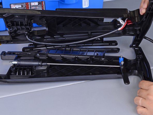
Unclip the clear hose from the back of the Rug Doctor.
-
-
Dieser Schritt ist noch nicht übersetzt. Hilf mit, ihn zu übersetzen!
-
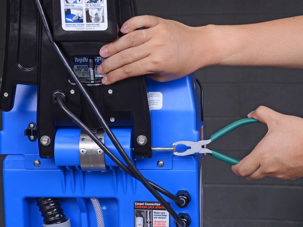
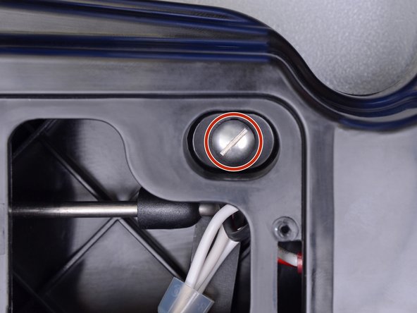
Use a 7/16" (11 mm OK) wrench to hold the handle axle while you use a 7/16" socket to remove the cap nut securing the axle end.
-
-
Dieser Schritt ist noch nicht übersetzt. Hilf mit, ihn zu übersetzen!
-
Support the handle with one hand. It will be loose after this step.
-
Use fingers or pliers to pull out the handle axle.
-
-
Dieser Schritt ist noch nicht übersetzt. Hilf mit, ihn zu übersetzen!
-
Detach the handle from the Rug Doctor and set it down.
-
-
Dieser Schritt ist noch nicht übersetzt. Hilf mit, ihn zu übersetzen!
-
Uncoil the power cable from the handle.
-
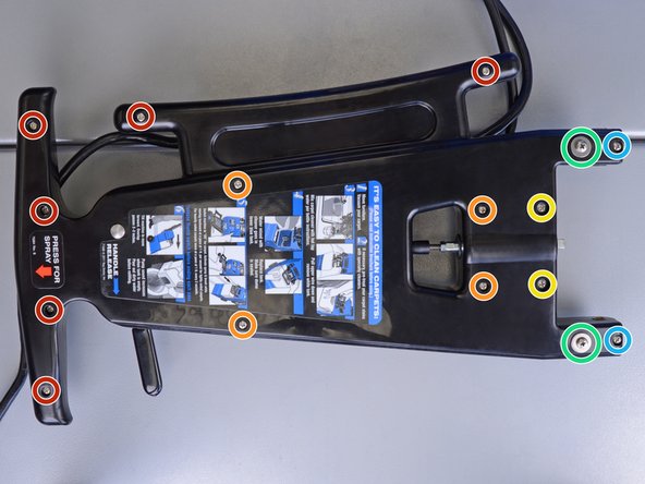
Remove the sixteen Phillips fasteners of the following lengths:
-
Six 22.7 mm machine screws
-
Four 35.3 mm machine screws
-
Two 25.2 mm (thicker) machine screws
-
Two 48.4 mm bolts with washers
-
Two 30.1 mm screws
-
-
-
Dieser Schritt ist noch nicht übersetzt. Hilf mit, ihn zu übersetzen!
-
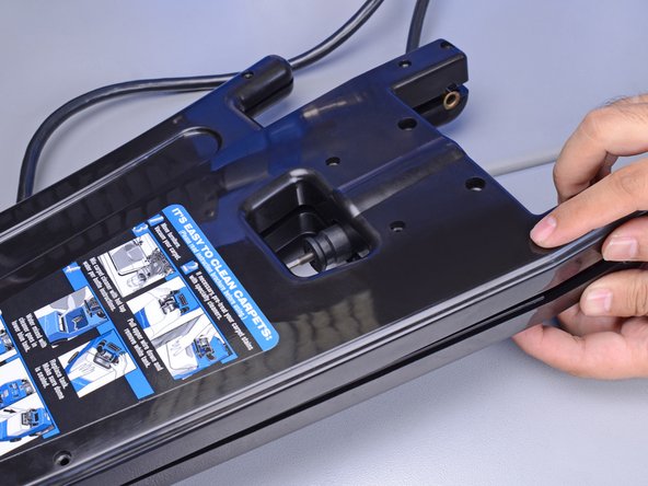
Separate the bottom edge of the handle slightly until the spring-loaded plunger pops out of its socket.
-
-
Dieser Schritt ist noch nicht übersetzt. Hilf mit, ihn zu übersetzen!
-
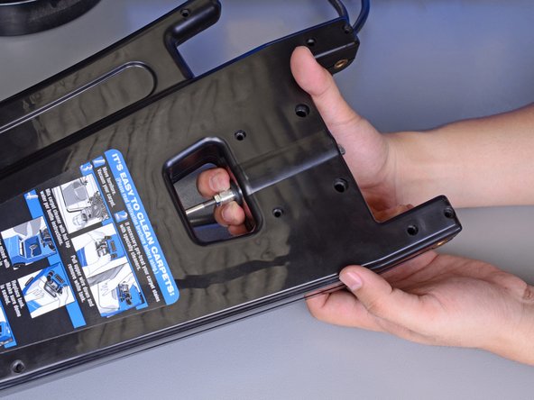
Use your fingers to push the black plunger down towards the bottom of the handle into position. This may take significant force.
-
Once the plunger slips into position, squeeze the the two handle halves together.
-
If that doesn't happen, check to see if the plunger is properly positioned, and that no wires are pinched.
-
Continue squeezing the two handle halves together while you reinstall the handle's lower screws.
-
-
Dieser Schritt ist noch nicht übersetzt. Hilf mit, ihn zu übersetzen!
-
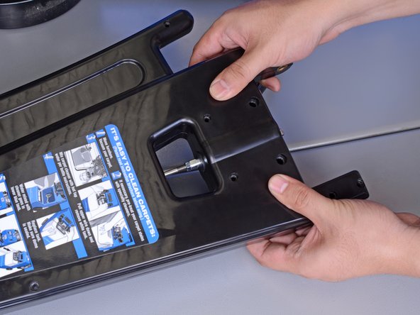
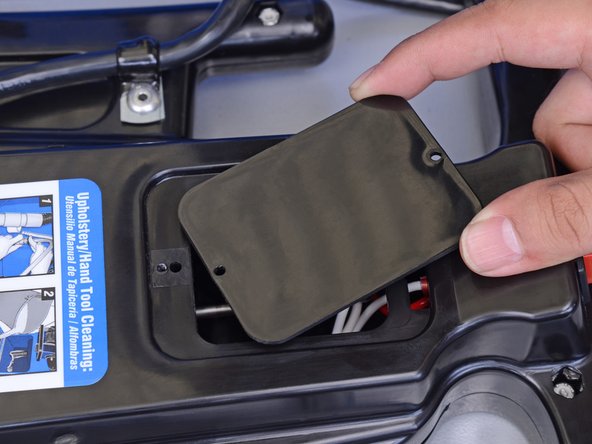
Remove the two 11.4 mm long Phillips screws holding the cover plate on the handle.
-
Remove the cover plate.
-
-
Dieser Schritt ist noch nicht übersetzt. Hilf mit, ihn zu übersetzen!
-
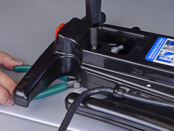
Use a pair of pliers to grasp the lip of the screw post close to the handle release lever.
-
While gripping the screw post, use a large flathead screwdriver to remove the machine screw mated to the other end of the screw post.
-
-
Dieser Schritt ist noch nicht übersetzt. Hilf mit, ihn zu übersetzen!
-
Pull the two handle halves apart.
-
-
Dieser Schritt ist noch nicht übersetzt. Hilf mit, ihn zu übersetzen!
-
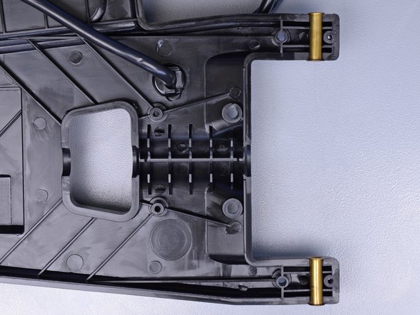
The lever mechanism components are properly stacked and oriented as shown.
-
Both brass bushings are in their sockets.
-
-
Dieser Schritt ist noch nicht übersetzt. Hilf mit, ihn zu übersetzen!
-
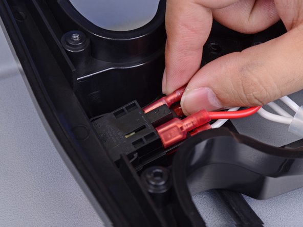
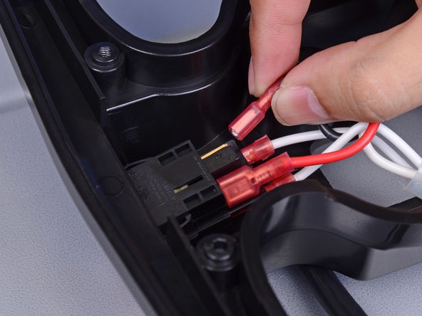
Red and black wires on the top sockets (order does not matter)
-
Two white wires on the bottom sockets
-
Use fingers or pliers to wiggle and pull the four connectors from the switch module.
-
-
Dieser Schritt ist noch nicht übersetzt. Hilf mit, ihn zu übersetzen!
-
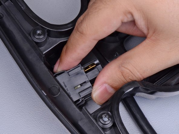
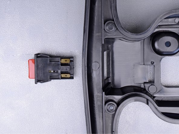
Use fingers or wide pliers to squeeze the black retainer tabs on each side of the button module.
-
While squeezing, wiggle and push the button module out of the front of the handle.
-
Remove the button module.
-


Rückgängig: Ich habe diese Anleitung nicht absolviert.
11 weitere Nutzer:innen haben diese Anleitung absolviert.

