Diese Übersetzung enthält möglicherweise noch nicht die neuesten Änderungen der Original-Anleitung. Hilf mit, die Übersetzung zu aktualisieren oder sieh dir die Original-Anleitung an.
Einleitung
Nur ein Zwischenschritt
Was du brauchst
-
-
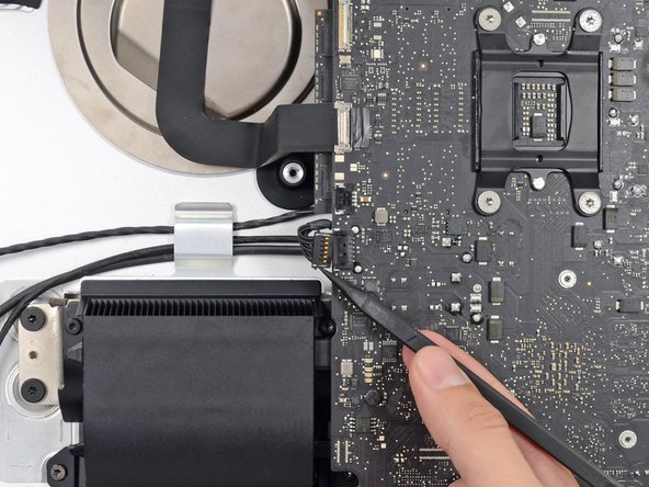
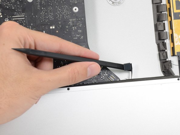
Drücke abwechselnd mit der Spudgerspitze an jeder Seite des Steckers vom linken Lautsprecherkabel und lasse so den Stecker "herauswandern".
-
-
-
Fädle das linke Lautsprecherkabel aus, indem du es direkt aus seiner Halteklammer hinten am Rückgehäuse herausziehst.
-
-
-
Löse in gleicher Weise wie im vorigen Schritt die SATA Datenkabel und Versorgungskabel aus der Halteklammer.
-
-
-
-
Klappe den metallenen Sicherungsbügel am Stecker des Kabels zur iSight Kamera mit dem flachen Ende des Spudgers hoch.
-
Ziehe das Kabel zur iSight Kamera gerade aus seinem Sockel auf dem Logic Board.
-
-
-
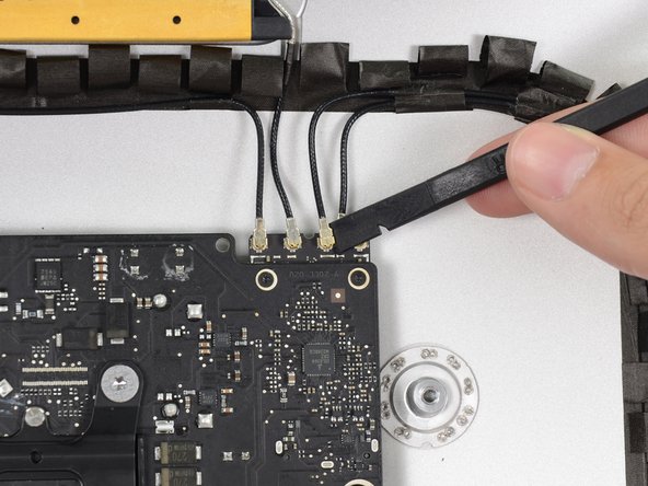
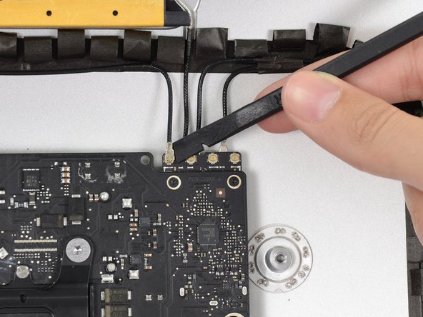
Löse die vier Antennenstecker mit der flachen Kante des Spudgers von der AirPort /Bluetooth Karte.
I broke off one of the antenna connectors when I took off the antenna wires, but the new 802.11ac card is working:) I seems the way to take off the wires is lifting it up from the wire side. In hindsight I just wasn´t careful enough.
how do I check a working logic board
If you have a pair of angled tweezers, they work well for grabbing under the connector so that you aren’t pulling on the wire. The head of the T10 screwdriver works well for pressing them back on.
iMac 2017 EMC 3069 this has the antenna brackets with two T5
-
-
-
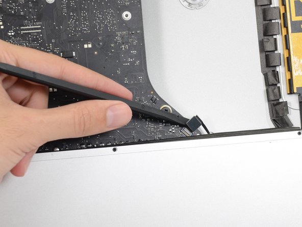
Hebele den Verbinder des Kabels zur Kopfhörerbuchse mit dem flachen Ende des Spudgers aus seinem Sockel auf dem Logic Board.
Unlike the rest of the connectors on the logic board, this one lifts up away from the board rather than to the side. That “Push the cable slightly to the right.” notation is after the connector is free.
-
-
-
Entferne folgende Torx T8 Schrauben, welche den Lüfterkanal am Rückgehäuse befestigen:
-
Zwei 6,3 mm Schrauben
-
Zwei 4,7 mm Schrauben
Weirdly, these screws didn’t work with my T8 driver. Not with T6 or T10.
Every other screw (to this point) has been fine. Hmm.
??? The T8 worked fine for me. Not sure what the difference would be.
Fare molta attenzione alla vite in fondo a destra, è facile (soprattutto se la punta del proprio cacciavite non è magnetizzata) che la vite si perda sotto alla Logic board. Se la punta del cacciavite non è magnetizzata consiglio o di utilizzare un magnete esterno o di utilizzare delle pinze mentre si svita la vite in modo da non incorrere in questo problema.
-
-
-
Entferne die vier 7,2 mm Torx T10 Schrauben, welche das Logic Board am Rückgehäuse befestigen.
When reinstalling the logic board, install four screws loose. Insert thumb drives into the back in all slots to ensure alignment. Once aligned, then tighten screws.
On some models there is a tiny microphone cable connector, just above the lower left logic board screw. Remove by carefully pulling straight down. There is also a piece of insulating plastic w/adhesive on top of the screw which can be pulled off prior to removal. Save and reuse with the same screw on installation.
-
-
-
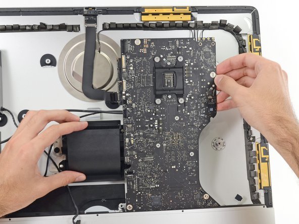
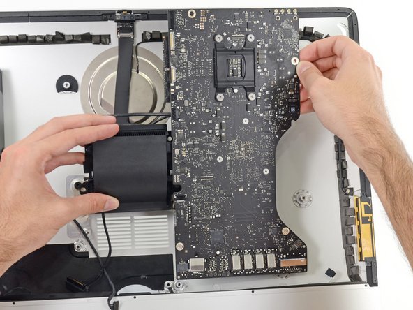
Kippe die Oberkante des Logic Boards weg vom Rückgehäuse.
-
Hebe das Logic Board gerade hoch und aus dem iMac heraus.
When inserting the logic board back, pay attention of the position of the I/O connectors. When it is back in place, put a USB / Thunderbolt cable into the connectors to ensure the perfect alignment.
This is fantastic advice. I used a combination of USB and display port plugs to ensure proper alignment and help keep the logic board steady while i screwed it back in. Thank you!!
kazoodac -
ive gotten this far and i still have one question, i’m replacing my HDD With A SSD should i also remove the original Blade drive ? and run exclusively off the ssd, ? i wasn’t 100 on whether or not i was getting the fusion set up so i’m not in possession of a upgraded blade, so i though this was a good question id hadn’t seen asked.
-


Um dein Gerät wieder zusammenzusetzen, folge den Schritten in umgekehrter Reihenfolge.
Um dein Gerät wieder zusammenzusetzen, folge den Schritten in umgekehrter Reihenfolge.
Besonderer Dank geht an diese Übersetzer:innen:
85%


Diese Übersetzer:innen helfen uns, die Welt zu reparieren! Wie kann ich mithelfen?
Hier starten ›


As noted in the right speaker cable section, the two corners of the connector are latches that need to be pushed toward the center of the connector to release. This is easily done with the pointed end of the spudger. Once the two corner latches are released, the connector comes apart easily.
Fred Heineman - Antwort