Kevin Pattison as you have probably already figured out, Apple suffers from total paranoia and delusions of grandeur. All of their schematics etc. Appear to be managed through “For your eyes only” security cleared personnel. Anybody violating their NDA will be punished to the full extend of the law, which of course is fully supporting companies like Apple. Support this https://repair.org/stand-up to stop the insanity. Anyhow, enough of that.
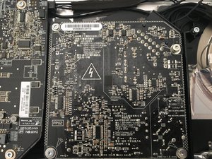
The PSU is a Delta ADP-200DF and a search on that may reveal more. In the meantime, I would use the pins listed for the test points. Use your multimeter to measure those on your actual PSU:
Pin 1
Ground
Pin 3
5V power for Hard Drive(s). Note: If present, the 12V power will come directly from the Power Supply to the Hard Drive thru the power harness cable.
Pin 4
Standby 12V power (permanent power coming from power supply, present as long as AC cable is connected, even if computer is off)
Pin 6
Backlight Control pulse width modulated signal (from logic board to LED backlight board, to adjust the backlight level setting according to user setup)
Pin 11
12V Run-Mode power to logic board (coming from power supply, present as long as system is on or asleep)
Pin12
Power On Request signal (from logic board to power supply when power button is pressed)
Pin 13
Backlight Enable (signal from logic board to Backlight Controller board, to enable backlight)
Pin 1 should be marked on the board. If you have any difficulties with that post some images of your PSU with your question. Bilder zu einer vorhandenen Frage hinzufügen
War diese Antwort hilfreich?
Bewertet
Rückgängig machen
Bewertung
3
Abbrechen
Schau durch den Thread, bis du den richtigen Platz für diesen Kommentar gefunden hast. Klicke dann auf "Den Kommentar diesem Post zuordnen", um ihn zu verschieben.