Hi @tiffanylaw ,
There is nothing obvious showing in the pictures so it will come down to doing some tests, initially static testing (without the power connected) but after that it will need to be with the power connected.
If neither you or your son has any experience testing when exposed lethal voltages are present then don’t do it. It is not worth it
(click on image to enlarge for better viewing).
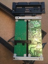
I’ve highlighted some points of interest in the image above where you may wish to check first.
With the power disconnected (green arrows) use an Ohmmeter:
check that the fuse on the ‘power’ board is OK i.e. short circuit measurement shown on Ohmmeter
can’t see it to well but if the regulator shown on the ‘amp’ board is a TPS54334 then these are prone to failure over time.
Not quite sure what you would measure when testing the regulator with an Ohmmeter in this particular circuit but you shouldn’t see a short circuit or an open circuit when testing across the pins. There are actually two regulators in the same package
If it is faulty and you cannot find a direct replacement a MP2307 is an equivalent component.
You will need smd (surface mounted device) soldering tools and skills to remove / replace the component
If it is determined from the static tests that the two check points suggested are both OK (green arrows) then you will have to connect the power and perform “live” testing. See note above re testing live circuits.
Again can’t see it too well and I haven’t got a schematic to work from but the red arrow points to what I think is the STBY (standby) power lead going from the power board to the amp board. This should be a DC voltage, its’ value is unknown to me, but given the regulator operates at anywhere between 4.75V DC to 28V DC you shouldn’t see any DC voltage higher than the 28V DC
Check if there is a DC voltage on the lead.
If there isn’t then there is a problem in the power board.
If there is then there is a problem on the amp board as the STBY power is to let the amp board “know” that power is available and it switches on the power light.
Be aware that there is exposed lethal voltages on the power board when you’re doing this.
Hopefully this is a start
War diese Antwort hilfreich?
Bewertet
Rückgängig machen
Bewertung
7
Abbrechen
Schau durch den Thread, bis du den richtigen Platz für diesen Kommentar gefunden hast. Klicke dann auf "Den Kommentar diesem Post zuordnen", um ihn zu verschieben.


28 Kommentare
@tiffanylaw "The sound bar is working fine but there appears to be no power coming from the subwoofer" how and what did you already check? What works and what does not?
von oldturkey03
The sound bar powers up fine and works as usual but there appears to be no power to the separate subwoofer, there used to be a green light that appeared when the unit was on I believe and this is located on the front below the top speaker but this is not illuminated now.
I have tried plugging it into multi sockets and I have changed the fuse in the plug.
Any other ideas I could try would be greatly appreciated.
The only control on this unit is a power on button and a link button. Kind regards Tiffany.@oldturkey03
von Tiffany Law
Hi @tiffanylaw ,
Since the warranty is no longer a consideration, you will have to open the sub woofer up (with the power totally disconnected) and check if there is anything amiss on the control board or power board (there may only be one board) such as burnt out or ruptured components.
Post some close up images of the board(s) back here so that others may be able to help you further.
Here's how to do this
Bilder zu einer vorhandenen Frage hinzufügen
If you have a DMM (digital multimeter) and know how to use it, it may be a help in finding out what's wrong if nothing is obvious.
von jayeff
Ok thank you very much I will do this and post pics ASAP.
My son has a multimeter so he may be able to assist with showing me how to use it.
Thank you for your help. @jayeff
von Tiffany Law
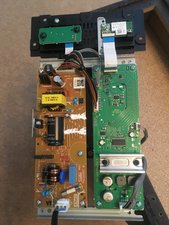
I have removed the back and this is what is inside.
I will have to wait for my son to get home for him to show me how to use the multimeter.
von Tiffany Law
23 weitere Kommentare anzeigen