Diese Version enthält möglicherweise inkorrekte Änderungen. Wechsle zur letzten geprüften Version.
Was du brauchst
-
Dieser Schritt ist noch nicht übersetzt. Hilf mit, ihn zu übersetzen!
-
Remove battery cover using a plastic opening tool or finger nail.
-
Slide opening tool to release clasps and remove battery cover.
-
-
Dieser Schritt ist noch nicht übersetzt. Hilf mit, ihn zu übersetzen!
-
With the cover removed, the battery will fall freely with a gentle shake.
-
-
Dieser Schritt ist noch nicht übersetzt. Hilf mit, ihn zu übersetzen!
-
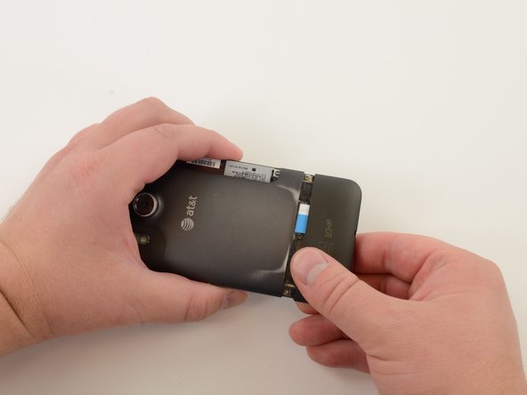
Remove SIM card cover by simultaneously squeezing cover and pulling it off of the phone.
-
-
Dieser Schritt ist noch nicht übersetzt. Hilf mit, ihn zu übersetzen!
-
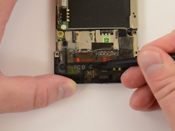
Remove Micro SD card by pushing it in to the phone. Spring-loaded clasp will release the card.
-
-
Dieser Schritt ist noch nicht übersetzt. Hilf mit, ihn zu übersetzen!
-
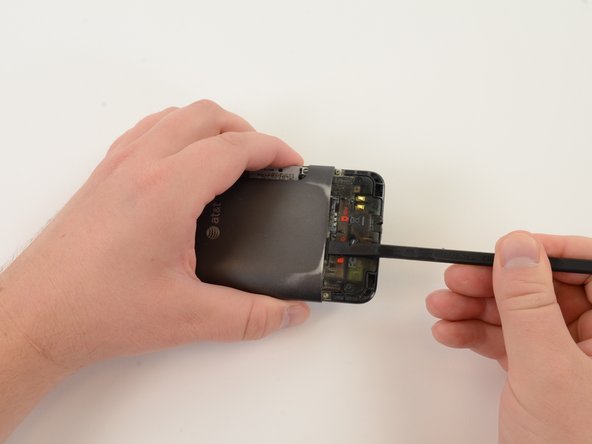
Use a curved metal spudger to remove GPS cover.
-
Probe underside of GPS cover until you can force a small opening between GPS cover and back cover of phone.
-
-
Dieser Schritt ist noch nicht übersetzt. Hilf mit, ihn zu übersetzen!
-
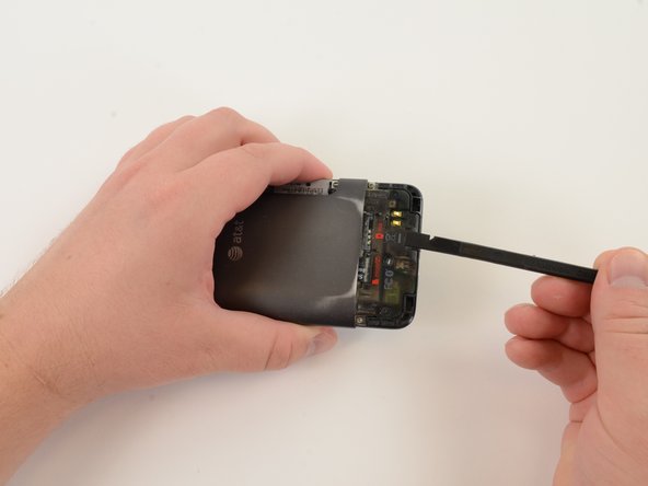
Insert plastic opening tool into gap between GPS cover and back cover of phone. Slide tool along GPS cover and pry the piece off.
-
-
Dieser Schritt ist noch nicht übersetzt. Hilf mit, ihn zu übersetzen!
-
Remove "VOID" sticker from screw.
-
-
Dieser Schritt ist noch nicht übersetzt. Hilf mit, ihn zu übersetzen!
-
Remove four 2.2mm T5 torx screws.
-
Remove one 4.5mm T5 torx screw.
-
-
Dieser Schritt ist noch nicht übersetzt. Hilf mit, ihn zu übersetzen!
-
Remove display cable shield.
-
Insert probing tool into screw hole and pull shield.
-
-
-
Dieser Schritt ist noch nicht übersetzt. Hilf mit, ihn zu übersetzen!
-
Peel off manufacturer's information sticker.
-
-
Dieser Schritt ist noch nicht übersetzt. Hilf mit, ihn zu übersetzen!
-
Lift volume button assembly out of the back case.
-
-
Dieser Schritt ist noch nicht übersetzt. Hilf mit, ihn zu übersetzen!
-
Push up on the back cover, wiggling cover back and forth, until it slides off.
-
-
Dieser Schritt ist noch nicht übersetzt. Hilf mit, ihn zu übersetzen!
-
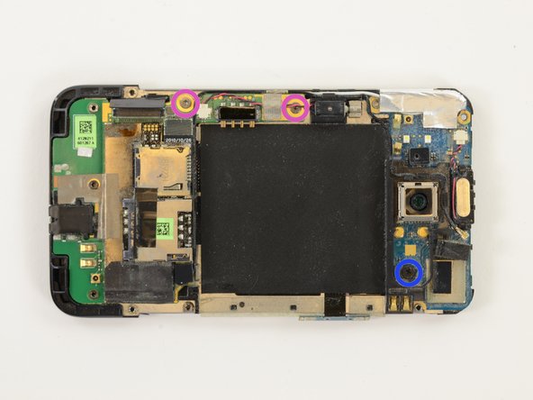
Remove "VOID" sticker.
-
Remove three 2.4mm T5 torx screws.
-
-
Dieser Schritt ist noch nicht übersetzt. Hilf mit, ihn zu übersetzen!
-
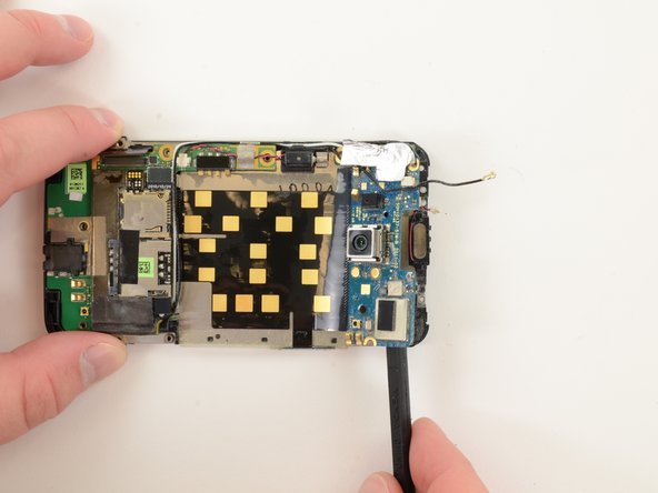
Apply pressure to the bottom of the plastic logic board shield and it will pop right off.
-
-
Dieser Schritt ist noch nicht übersetzt. Hilf mit, ihn zu übersetzen!
-
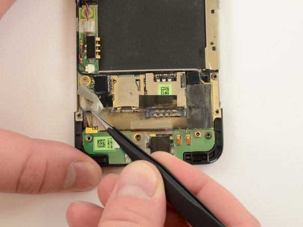
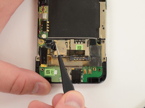
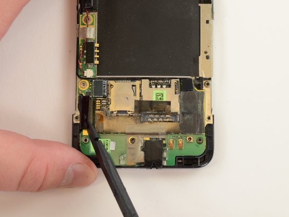
Pry display assembly connector off of lower logic board.
-
-
Dieser Schritt ist noch nicht übersetzt. Hilf mit, ihn zu übersetzen!
-
Remove speaker.
-
This rubber spacer is held on by a weak adhesive. Be careful with this during reassembly, as it may catch and crumple as you put the back panel back the phone.
-
-
Dieser Schritt ist noch nicht übersetzt. Hilf mit, ihn zu übersetzen!
-
Remove one 1.5mm #00 Phillips screw.
-
Remove two 2.5mm T5 torx screws.
-
-
Dieser Schritt ist noch nicht übersetzt. Hilf mit, ihn zu übersetzen!
-
Remove earpiece speaker connector.
-
-
Dieser Schritt ist noch nicht übersetzt. Hilf mit, ihn zu übersetzen!
-
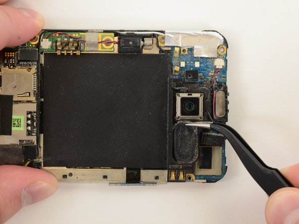
Pry off Bluetooth coaxial cable connector.
-
Unwind Bluetooth coaxial cable from plastic camera shield.
-
-
Dieser Schritt ist noch nicht übersetzt. Hilf mit, ihn zu übersetzen!
-
Pry off plastic camera shield.
-
-
Dieser Schritt ist noch nicht übersetzt. Hilf mit, ihn zu übersetzen!
-
Heat black Mylar shield for easier removal.
-
Peel off Mylar shield.
-
-
Dieser Schritt ist noch nicht übersetzt. Hilf mit, ihn zu übersetzen!
-
Gently separate upper logic board from mid chassis. The upper logic board is held to the mid chassis by copious amounts of strong adhesive.
-
-
Dieser Schritt ist noch nicht übersetzt. Hilf mit, ihn zu übersetzen!
-
Gently separate lower logic board from mid chassis. The lower logic board is held to the mid chassis by copious amounts of strong adhesive.
-
-
Dieser Schritt ist noch nicht übersetzt. Hilf mit, ihn zu übersetzen!
-
Once the adhesive-laden logic boards are separated from the mid chassis, the entire assembly easily comes off.
-
-
Dieser Schritt ist noch nicht übersetzt. Hilf mit, ihn zu übersetzen!
-
Blast the front panel with heat and pry between the display assembly and front panel bezel, working one or several guitar picks around the display assembly.
-
Once the display assembly is loosened from the front panel, it will fall away.
-
The front glass came off easily, but the digitizer was much more difficult to remove. The adhesive holding together the display assembly is much weaker than the adhesive holding the display assembly to the front panel.
-


Rückgängig: Ich habe diese Anleitung nicht absolviert.
17 weitere Nutzer:innen haben diese Anleitung absolviert.

