Einleitung
Use this guide to replace the heat sink or the thermal paste.
Be sure to apply a new layer of thermal paste before reinstalling your heat sink.
Was du brauchst
-
In diesem Schritt verwendetes Werkzeug:P5 Pentalobe Screwdriver Retina MacBook Pro and Air$5.99
-
Use a P5 Pentalobe driver to remove ten screws securing the lower case, of the following lengths:
-
Two 9 mm screws
-
Eight 2.6 mm screws
-
-
-
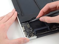
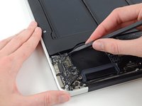
Wedge your fingers between the display and the lower case and pull upward to pop the lower case off the Air.
-
Remove the lower case and set it aside.
-
-
-
Grab the clear plastic pull tab attached to the battery connector and pull it parallel to the board toward the front edge of the Air.
-
-
-
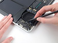
Use the flat end of a spudger to pry the I/O board cable connector up out of its socket on the I/O board.
-
-
-
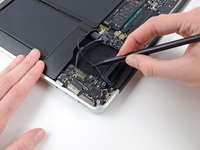
Carefully peel the I/O board cable from the adhesive securing it to the top of the fan.
-
-
-
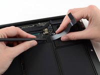
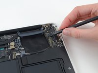
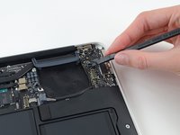
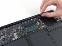
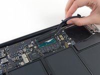
While gently pulling the I/O board cable upward near its connection to the logic board, use the flat end of a spudger to pry up on alternating sides of the connector to help "walk" it out of its socket.
-
Remove the I/O board cable.
-
-
-
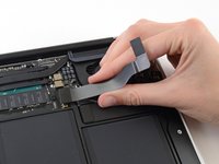
Use the tip of a spudger to carefully flip up the retaining flap on the fan cable ZIF socket.
-
-
-
-
Remove the following three screws securing the fan to the upper case:
-
One 3.6 mm T5 Torx screw
-
One 2.7 mm T5 Torx screw
-
One 3.6 mm T5 Torx screw with a short head
-
-
-
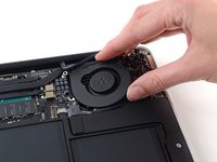
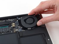
Lift the fan from the I/O board side and pull it free from the upper case.
-
Removing the fan will also disconnect the fan ribbon cable. Be careful not to snag it.
-
-
-
Disconnect the I/O board by pulling its power cable away from its socket on the logic board.
-
-
-
Use the flat end of a spudger to pry the left speaker cable connector up and out of its socket on the I/O board.
-
-
-
Use the tip of a spudger to carefully flip up the retaining flap on the microphone ribbon cable ZIF socket.
-
-
-
Remove the single 3.6 mm T5 Torx screw securing the I/O board to the upper case.
-
-
-
Gently de-route the camera cable from its notch on the I/O board and push it out of the way with the tip of a spudger.
-
-
-
Lift the I/O board from the logic board side and pull it free from the upper case.
-
Removing the I/O board will also disconnect the microphone ribbon cable. Be careful not to snag it.
-
-
-
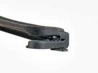
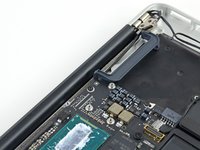
Remove the two 4.9 mm T8 Torx screws securing the antenna cable retainer on the left display hinge to the upper case.
-
-
-
Push the antenna cable retainer out of the way and remove the single 3 mm T5 Torx screw securing the end of the heat sink to the upper case.
-
-
-
Remove the four 2.5 mm T5 Torx screws securing the heat sink to the logic board.
-


To reassemble your device, follow these instructions in reverse order.
To reassemble your device, follow these instructions in reverse order.
Rückgängig: Ich habe diese Anleitung nicht absolviert.
13 weitere Personen haben diese Anleitung absolviert.


Ein Kommentar
Ho fatto tutto il procedimento con il fiato sospeso e alla fine ero convinto di aver rotto qualcosa ma non era vero. Tutto è andato bene la laptop non è esplosa. Io dovevo solo rimuovere il heatsink per sostituire la pasta termica, Dio mio quante viti da smontare, pensavo di arrivare direttamente e scoperchiare la CPU. Grazie.