Diese Version enthält möglicherweise inkorrekte Änderungen. Wechsle zur letzten geprüften Version.
Was du brauchst
-
-
Entferne die folgenden 10 Schrauben, die das Gehäuseunterteil mit dem Deckel verbinden:
-
Drei 13.5 mm Kreuzschlitzschrauben
-
Sieben 3 mm Kreuzschlitzschrauben
-
-
-
Zwänge deine Finger zwischen das Gehäuseunterteil und die Lüftungsschlitze und ziehe das Unterteil nach oben, um die Clips zu lösen, mit denen das Gehäuseunterteil am Deckel befestigt ist.
-
Entferne das Gehäuseunterteil.
-
-
-
Falls vorhanden, ziehe die kleine Plastiklasche am Akkustecker gegen die Vorderkante des Geräts. Bei Modellen von Ende 2011 hat der Stecker keine Lasche und ist einfach direkt im Motherboard eingesteckt. In diesem Fall ziehe den Stecker gerade nach oben, um ihn zu entfernen.
-
-
Dieser Schritt ist noch nicht übersetzt. Hilf mit, ihn zu übersetzen!
-
Use the tip of a spudger to push the small plastic cable retainer away from the camera cable socket for enough clearance to remove the camera cable.
-
-
Dieser Schritt ist noch nicht übersetzt. Hilf mit, ihn zu übersetzen!
-
Pull the camera cable toward the optical drive opening to disconnect it from the logic board.
-
-
Dieser Schritt ist noch nicht übersetzt. Hilf mit, ihn zu übersetzen!
-
Carefully pull the Bluetooth cable toward the fans to disconnect it from the Bluetooth board.
-
-
Dieser Schritt ist noch nicht übersetzt. Hilf mit, ihn zu übersetzen!
-
Use the flat end of a spudger to peel the thin plastic cover off the top and sides of the Bluetooth board housing. For late-2011 models check out the other picture because the connector location is in a totally different location.
-
-
Dieser Schritt ist noch nicht übersetzt. Hilf mit, ihn zu übersetzen!
-
Use the flat end of a spudger to pry the Bluetooth antenna connector up and off its socket on the Bluetooth board.
-
-
Dieser Schritt ist noch nicht übersetzt. Hilf mit, ihn zu übersetzen!
-
De-route the camera cable from the slot molded into the Bluetooth board housing.
-
-
-
Dieser Schritt ist noch nicht übersetzt. Hilf mit, ihn zu übersetzen!
-
Remove the two 7.1 mm Phillips screws securing the camera cable retainer to the upper case.
-
Remove the camera cable retainer from the upper case.
-
-
Dieser Schritt ist noch nicht übersetzt. Hilf mit, ihn zu übersetzen!
-
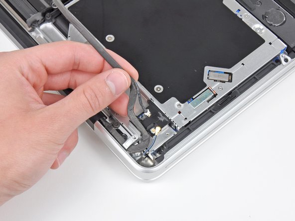
Lift the black plastic flap attached to the display data cable retainer and rotate it toward the DC-In side of the MacBook.
-
Pull the display data cable out of its socket.
-
-
Dieser Schritt ist noch nicht übersetzt. Hilf mit, ihn zu übersetzen!
-
Remove the two 7.1 mm Phillips screws securing the display data cable retainer to the upper case.
-
Remove the display data cable retainer.
-
-
Dieser Schritt ist noch nicht übersetzt. Hilf mit, ihn zu übersetzen!
-
Remove the two outer 6.8 mm T6 Torx screws from each of the two display brackets (four screws total).
-
-
Dieser Schritt ist noch nicht übersetzt. Hilf mit, ihn zu übersetzen!
-
While holding the display and upper case together with your left hand, remove the remaining T6 Torx screw from the lower display bracket.
-
-
Dieser Schritt ist noch nicht übersetzt. Hilf mit, ihn zu übersetzen!
-
Remove the last remaining T6 Torx screw securing the display to the upper case.
-
-
Dieser Schritt ist noch nicht übersetzt. Hilf mit, ihn zu übersetzen!
-
Grab the upper case with your right hand and rotate it slightly toward the top of the display so the upper display bracket clears the edge of the upper case.
-
Rotate the display slightly away from the upper case.
-
Lift the display up and away from the upper case, minding any brackets or cables that may get caught.
-
-
Dieser Schritt ist noch nicht übersetzt. Hilf mit, ihn zu übersetzen!
-
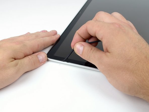
Insert a plastic opening tool underneath the black rubber gasket at the bottom left corner of the display assembly.
-
Gently pry the wide edge of the gasket up from the back case.
-
-
Dieser Schritt ist noch nicht übersetzt. Hilf mit, ihn zu übersetzen!
-
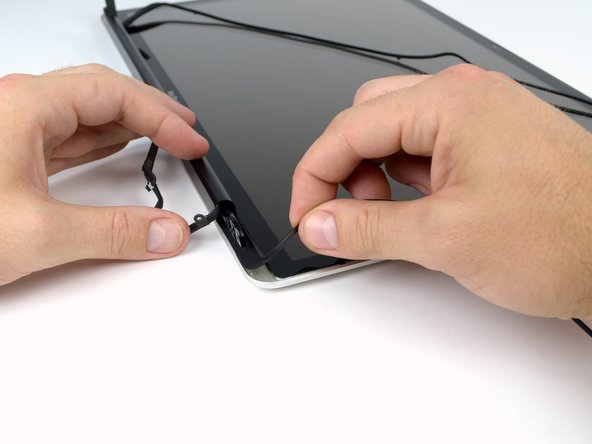
Starting with the freed corner, pull the left gasket off the left side of the display assembly.
-
-
Dieser Schritt ist noch nicht übersetzt. Hilf mit, ihn zu übersetzen!
-
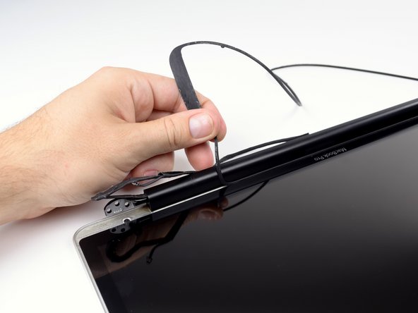
Continue pulling the display gasket off the display assembly across the top edge.
-
-
Dieser Schritt ist noch nicht übersetzt. Hilf mit, ihn zu übersetzen!
-
Continue pulling the display gasket off the display assembly down the right side.
-
Pull the gasket off the bottom edge of the display to completely free it and set it aside.
-
-
Dieser Schritt ist noch nicht übersetzt. Hilf mit, ihn zu übersetzen!
-
Before starting, be sure to clean the display glass with a lint-free cloth moistened with a mild solution; it will make the suction cup adhere better, and will make checking for dust on reassembly easier.
-
With the heat gun set to low, start by heating the outer black border near the upper right corner of the glass panel.
-
-
Dieser Schritt ist noch nicht übersetzt. Hilf mit, ihn zu übersetzen!
-
With the panel sufficiently heated, fasten a heavy-duty suction cup near the lower right corner of the display glass.
-
To attach the suction cups we sell, first position the suction cup with the movable handle parallel to the face of the glass panel. While lightly holding the suction cup against the glass, raise the movable handle until it is parallel with the other handle.
-
Gently lift the corner of the display glass enough to insert a guitar pick between it and the display assembly.
-
Use the guitar pick to gently pry up the adhesive securing the front glass to the display.
-
Pry up the glass panel along the right edge of the display up to the halfway point.
-
Leave the guitar pick in place halfway up the right side of the display and remove the suction cup.
-
-
Dieser Schritt ist noch nicht übersetzt. Hilf mit, ihn zu übersetzen!
-
Use a heat gun to soften the adhesive under the display glass along the right and top edges of the display.
-
Attach a suction cup to the upper right corner of the front glass panel.
-
Pull up on the glass panel while you use a second guitar pick to separate it from the rest of the display assembly.
-
Continue working along the right edge of the front display glass until it is separated from the display.
-
-
Dieser Schritt ist noch nicht übersetzt. Hilf mit, ihn zu übersetzen!
-
Work along the top edge of the display assembly, carefully prying the adhesive up with the guitar pick.
-
Stop prying about an inch before you reach the iSight camera. Leave the guitar pick in place and remove the suction cup.
-
-
Dieser Schritt ist noch nicht übersetzt. Hilf mit, ihn zu übersetzen!
-
Repeat steps 22 through 24 for the left side and the left top edge of the display.
-
-
Dieser Schritt ist noch nicht übersetzt. Hilf mit, ihn zu übersetzen!
-
After prying up the three edges of the display glass, you should have four guitar picks resting underneath the panel, as shown.
-
-
Dieser Schritt ist noch nicht übersetzt. Hilf mit, ihn zu übersetzen!
-
With the heat gun set to low, heat the bottom edge of the display to soften the adhesive holding the glass in place.
-
Slowly lift the top edge of the glass panel and gently rotate it out of the display.
-


Rückgängig: Ich habe diese Anleitung nicht absolviert.
8 weitere Nutzer:innen haben diese Anleitung absolviert.

