Einleitung
Die Tasten und das D-Pad des Nintendo Switch Pro-Controllers sind die wichtigsten Steuerelemente des Controllers. Die Tasten müssen möglicherweise ersetzt werden, wenn sie nicht mehr reagieren. Weitere Informationen findest du in unserer Anleitung zur Fehlerbehebung.
Achte bei der Demontage auf scharfe Kanten, es gibt ein paar freiliegende Plastikstücke, an denen du dich schneiden könntest.
Was du brauchst
-
-
Drehe den Controller so um, dass der Aufkleber mit der Modellnummer nach oben zeigt.
-
Entferne die beiden schwarzen 8,4 mm Flachkopf-Kreuzschlitzschrauben mit einem JIS #00-Bit, mit denen die Handgriffe am Ende verschraubt sind.
-
-
-
Ziehe die Abdeckungen der Griffe vorsichtig vom Controller.
-
-
-
Entferne die vier silberfarbenen 6,8 mm langen JIS-Schrauben #00, mit denen die durchsichtige Abdeckung befestigt ist.
-
-
-
Löse die durchsichtige Abdeckung mit deinem Fingernagel ab.
-
-
-
Entferne den Lithium-Ionen-Akku, indem du ihn mit deinem Fingernagel oder einem Öffnungswerkzeug an der linken Seite anhebst.
-
-
-
-
Entferne die fünf 6 mm Kreuzschlitzschrauben auf der Rückseite des Controllers:
-
Die beiden Gehäuseschrauben über den Handgriffen und eine Schraube unter dem Akku sitzen nicht sehr tief. Diese Schrauben können leicht entfernt werden.
-
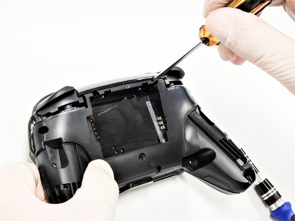
Die beiden Schrauben neben der ZR und der ZL Schultertasten sitzen in tiefen Löchern. Um an sie heranzukommen musst du eine Bitverlängerung oder einen Schraubendreher mit langem Schaft verwenden.
the 2 screws up at the top are unreachable with the standard fixit kit just a heads up
Seconded. the screws are located too deep below the plastic slot, and the bit holding bulge is too wide for the small aperture (similarly with the flexible extension). the bit length is too shallow to reach.
An alternative driver with a much narrower & longer shaft is required, which will likely not come with interchangeable bits.
I would say it is possible to reach the top left screw, just not the top right - there is a gap in the top left that allows you to slightly bend the standard driver outward to turn it while still making adequate contact.
An update: I was actually able to remove the top right one in a really hacky way - inserting the Phillips #0 bit into the #4 hex bit, and then using that in the standard driver. This added just enough length to successfully reach and make full contact with the screw!
Using the #4 hex bit as an extension was the exact "hack" I needed to get rid of the drift finally. Thank you. You're a lifesaver.
Das #4 Hex Bit als Verlängerung für das Kreuzschlitz Bit zu nutzen ist zwar etwas eng, aber es erspart einem wirklich einen zusätzlichen Schraubendreher.
-
-
-
Nimm die Kunststoffabdeckung des Controllers behutsam ab.
Didn't realize there is adhesive holding the front cover onto the unit. It's located inside of the handles. Just a bit of force there helped, just be careful of the cable.
-
-
-
Drücke den schwarzen Sicherungsbügel am ZIF-Anschluss mit der Spitze eines Plektrums zum Öffnen nach oben.
Having just completed this repair, I noted that this ribbon cable can disconnect on either side. It is easier to disconnect and reconnect from the other side than what is shown in my experience.
@acestronautical is right! much easier to remove the ribbon cable from the button board, connect to the base board and then connect back to the button board. Thank you @acestronautical
-
-
-
Löse das Verbindungskabel mit deinen Fingern oder einer stumpfen Pinzette aus seinem Anschluss.
You don't need to disconnect this as long as you are fine with keeping it close by so as not to rip the ribbon cable.
-
-
-
Entferne die zwei 6,8 mm langen Schrauben auf der oberen Platine mit einem Kreuzschlitzschraubendreher #00.
-
-
-
Nutze einen Spudger, um den Verriegelungsbügel am ZIF-Stecker zu öffnen.
-
-
-
Entferne das schwarze Flachbandkabel vom Steckverbinder.
What do I do if the connector snaps off? Is it fixable with solder or electrical tape or should I give up hope?
This ribbon cable is difficult to reconnect, quality tweezers are required. I was unable to slide the ribbon cable in to where I could no longer see the traces. Take note of how much ribbon cable is exposed before disconnecting so that you can have an easier time judging when the cable is fully inserted upon reconnecting.
-
-
-
Drehe die beiden 5 mm langen Kreuzschlitzschrauben heraus, mit denen die Leiterplatte befestigt ist.
There’s one more screw - in this picture, on the left. The junction of the body and left grip, right behind the ABXY buttons.
Hi @mattrausch, thanks for your comment. You're right, the circuit board is held by two screws. I've updated this step.
-
-
-
Entferne die Taste, die du ersetzen möchtest mit den Fingern oder einer Pinzette. Ziehe sie dazu aus ihrer Öffnung heraus.
-


Um dein Gerät wieder zusammenzubauen, folge diesen Anweisungen in umgekehrter Reihenfolge.
Um dein Gerät wieder zusammenzubauen, folge diesen Anweisungen in umgekehrter Reihenfolge.
Rückgängig: Ich habe diese Anleitung nicht absolviert.
21 weitere Nutzer:innen haben diese Anleitung absolviert.
Besonderer Dank geht an diese Übersetzer:innen:
100%

Diese Übersetzer:innen helfen uns, die Welt zu reparieren! Wie kann ich mithelfen?
Hier starten ›

Team

Cal Poly, Team S11-G2, Regan Fall 2019 Mitglied von Cal Poly, Team S11-G2, Regan Fall 2019
CPSU-REGAN-F19S11G2
5 Mitglieder
42 Anleitungen geschrieben
3 Kommentare
On re-assembly, you may have trouble getting the top circuit board and shoulder button support structure to snap into place. It’s easiest to get the circuit board around the right analog stick hole, and push it all the way down until it is in place, then to secure the shoulder button support structure.
Make sure the “Home” button clear plastic light spreader (a clear irregular circle-shaped piece) is in place on top of the home button assembly, or it will give the home button a “sunken” appearance.
Worked well, thank you. Had a gooey X button that needed to be cleaned.
Be carefull, these screws are super easy to strip even with the right tools.
Lukas Eberharter - Antwort
I tried editing these instructions after I had trouble with stripping screws, but it doesn't seem to take. The issue is that these are JIS and not Phillips screws. They are VERY similar looking but a Phillips head screwdriver will strip the screws.
Isaac Webb - Antwort
I tried using a Philips #00 screwdriver but it didn’t work
vincent ingrassia - Antwort