Einleitung
Use this guide to replace the depth sensor in your HTC Vive XR Elite.
Was du brauchst
-
-
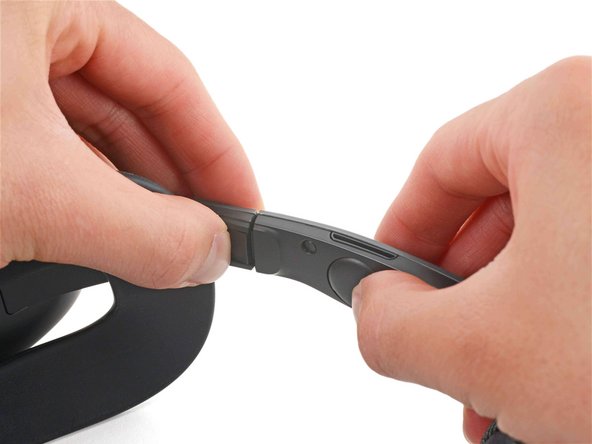
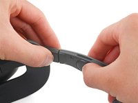
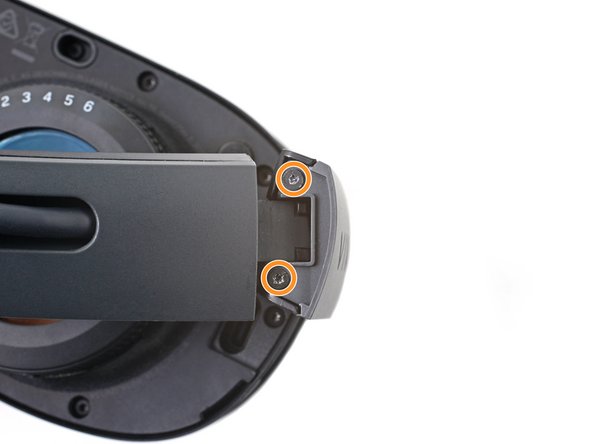
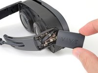
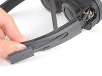
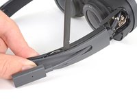
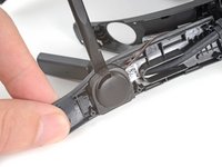
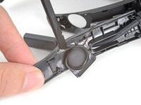
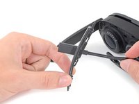
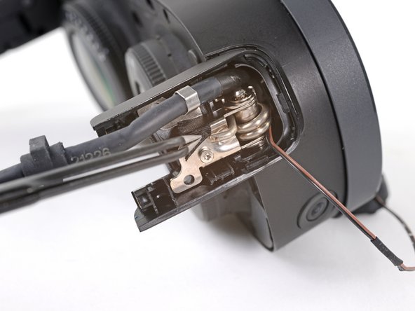
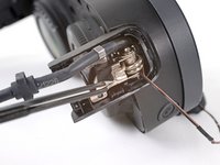
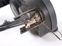
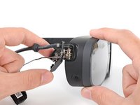
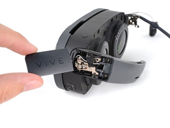
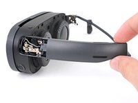
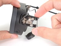
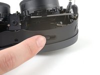
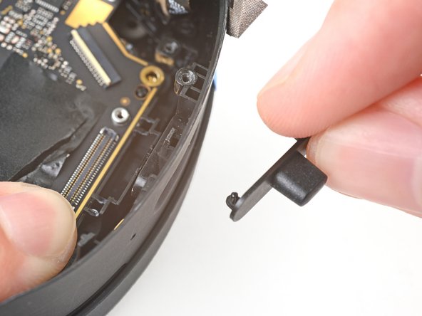
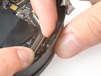
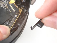
Press the release button on the right battery cradle temple slot.
-
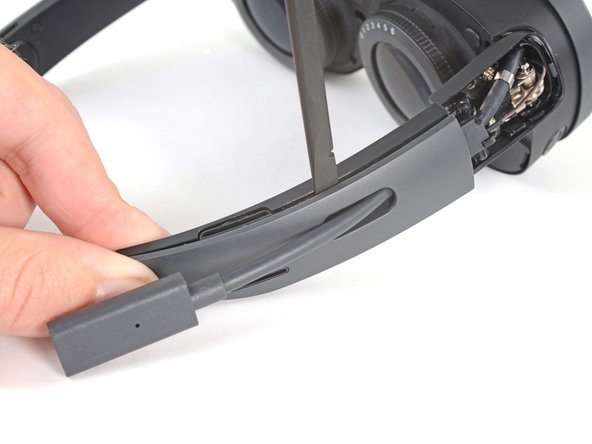
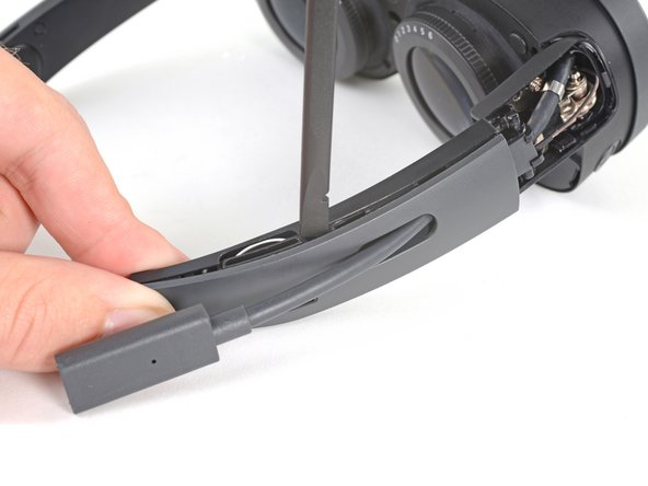
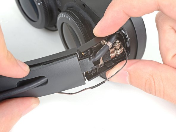
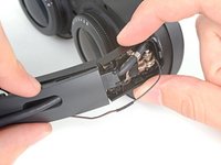
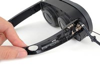
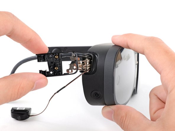
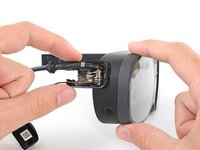
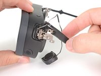
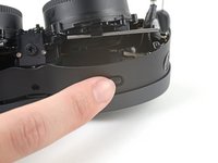
Pull the battery cradle away from the right temple slot to disconnect it.
-
-
-
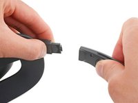
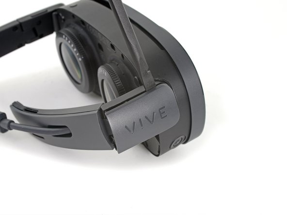
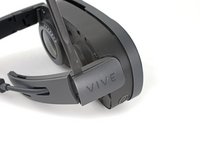
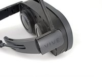
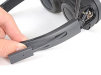
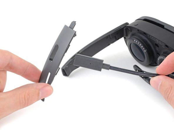
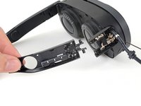
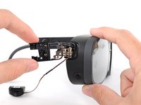
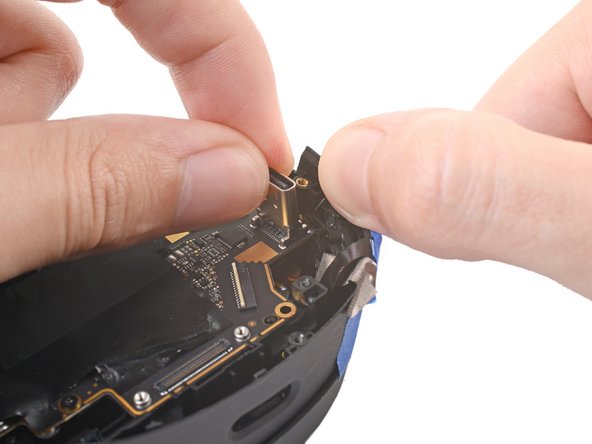
Separate the headset and battery cradle.
-
-
-
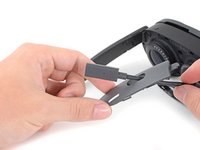
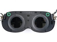
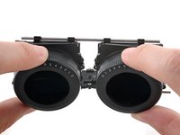
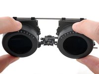
Grip the middle of the face cushion with your fingers and pull back to remove it.
-
-
In diesem Schritt verwendetes Werkzeug:Tweezers$4.99
-
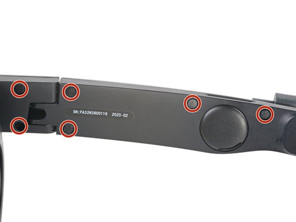
Use tweezers to remove the six screw covers from the right temple.
-
-
-
Use a T5 Torx screwdriver to remove the six 4.9 mm‑long screws securing the two right temple halves.
-
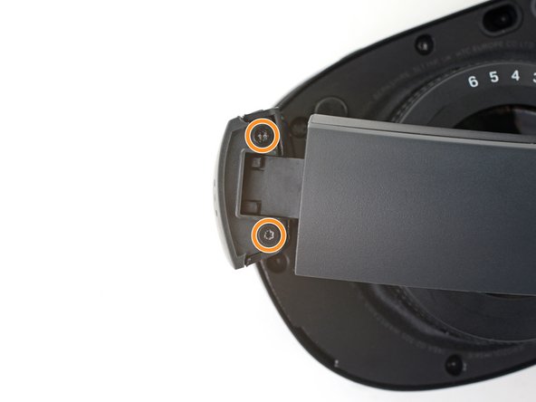
Use a T5 Torx screwdriver to remove the two 3.5 mm‑long screws securing the right hinge cover.
-
-
-
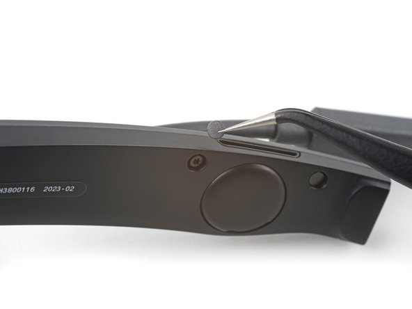
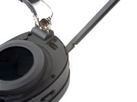
Insert the flat end of a spudger in the gap between the right outer and inner hinge covers.
-
Slide the spudger along the gap to separate the clips securing the outer hinge cover.
-
Remove the outer hinge cover.
-
-
-
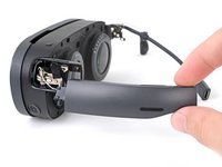
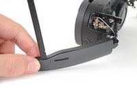
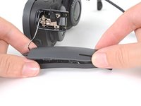
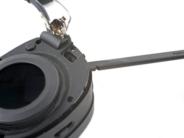
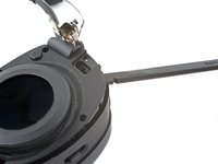
Insert the flat end of a spudger in the gap between the outer and inner temple.
-
Slide the spudger along the gap to separate the clips securing the outer temple.
-
-
In diesem Schritt verwendetes Werkzeug:Tesa 61395 Tape$6.99
-
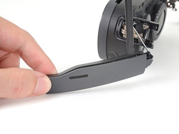
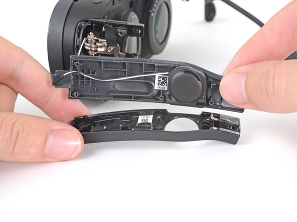
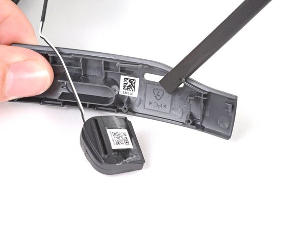
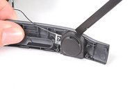
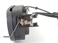
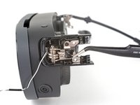
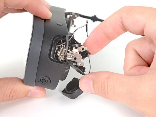
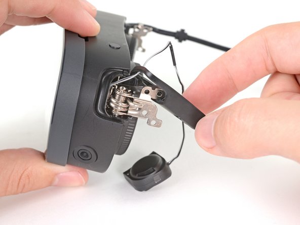
Rotate the outer temple towards you to access the speaker.
-
Slide the flat end of a spudger under the speaker to separate its adhesive.
-
-
-
Use tweezers to peel back the black tape covering one of the inner hinge cover screws.
-
-
-
Use a T5 Torx screwdriver to remove the two screws securing the inner hinge cover:
-
One 3.1 mm‑long screw
-
One 4.9 mm‑long screw
-
-
-
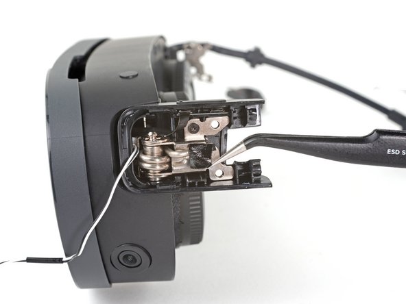
Rotate the inner hinge cover off its groove in the frame.
-
Thread the inner hinge cover off of the USB-C and speaker cables and remove it.
-
-
In diesem Schritt verwendetes Werkzeug:Tweezers$4.99
-
Use tweezers to remove the six screw covers from the left temple.
-
-
-
Use a T5 Torx screwdriver to remove the six 4.9 mm‑long screws securing the two left temple halves.
-
Use a T5 Torx screwdriver to remove the two 3.5 mm‑long screws securing the left hinge cover.
-
-
-
Insert the flat end of a spudger in the gap between the left outer and inner hinge covers.
-
Slide the spudger along the gap to separate the clips securing the outer hinge cover.
-
Remove the outer hinge cover.
-
-
-
Insert the flat end of a spudger in the gap between the outer and inner temple.
-
Slide the spudger along the gap to separate the plastic clips securing the outer temple.
-
-
-
Pull the outer temple off of its inner half to completely release its plastic clips.
-
-
In diesem Schritt verwendetes Werkzeug:Tesa 61395 Tape$6.99
-
Slide the flat end of a spudger under the speaker to separate its adhesive.
-
Let the speaker rest next to the headset before continuing.
-
-
-
Use tweezers to peel back the black tape covering one of the inner hinge cover screws.
-
-
-
Use a T5 Torx screwdriver to remove the two screws securing the inner hinge cover:
-
One 3.5 mm‑long screw
-
One 4.9 mm‑long screw
-
-
-
Rotate the inner hinge cover off its groove in the frame.
-
Let the cover hang off its volume button cable for now.
-
-
-
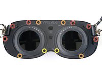
Use a T5 Torx screwdriver to remove the 12 screws securing the face plate:
-
Six 3.5 mm‑long screws
-
Four 4.9 mm‑long screws
-
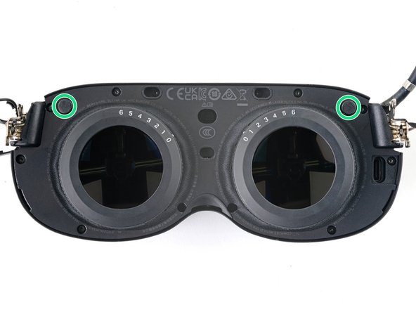
Two 6.5 mm‑long screws
-
There are two magnets at the top corners of the face plate. As you remove nearby screws, they might stick to them.
-
-
-
Insert the flat end of the spudger in the gap between the frame and the bottom right corner of the face cover.
-
Pry up with the spudger to release the clips securing the face cover.
-
-
-
Repeat the prying process for the middle and bottom left portions of the face cover.
-
-
-
Lift the face cover and rotate it over the top of the frame.
-
Lay the face cover face up before continuing.
-
-
-
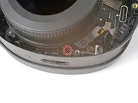
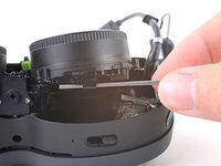
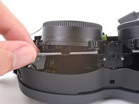
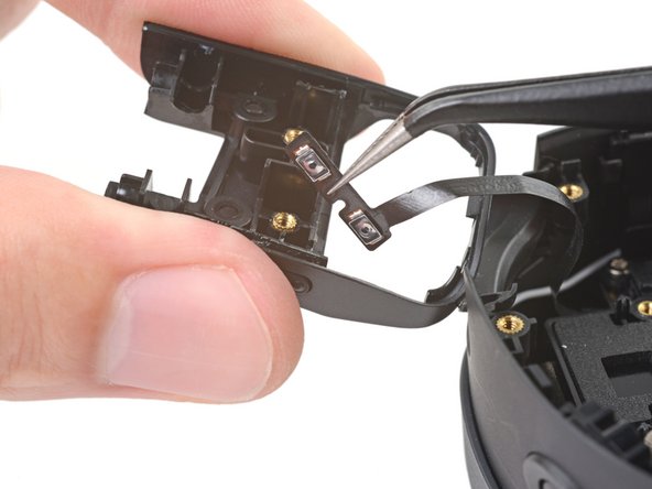
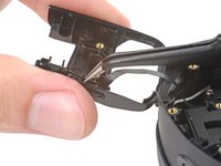
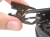
Use a T5 Torx screwdriver to remove the two 3.3 mm‑long screws securing the proximity sensor cable.
-
-
-
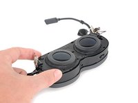
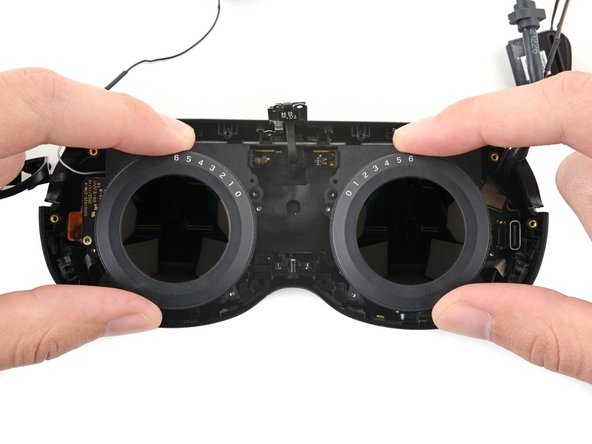
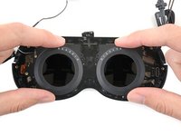
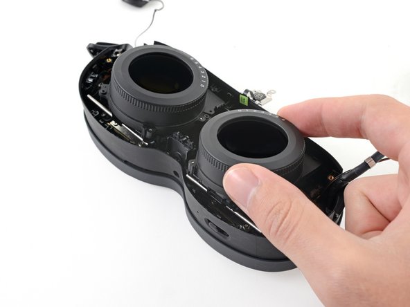
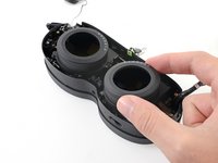
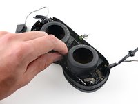
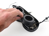
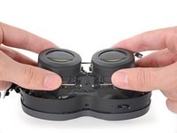
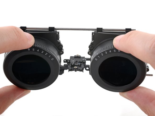
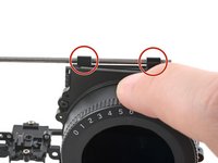
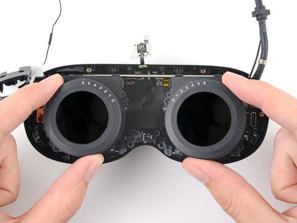
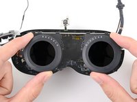
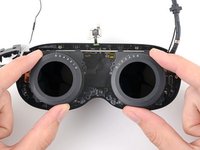
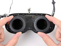
Pull the two lenses outward so they're as far apart as possible.
-
-
-
-
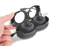
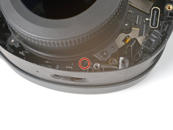
Use a T5 Torx screwdriver to remove the four screws securing the lens assembly:
-
Three 4.9 mm‑long screws
-
One 3.3 mm‑long screw
-
-
In diesem Schritt verwendetes Werkzeug:Tweezers$4.99
-
Use tweezers to pull the left screw bracket of its post in the frame.
-
Repeat this process for the right bracket.
-
-
-
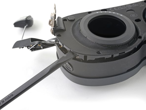
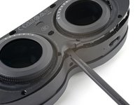
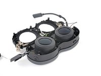
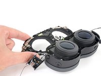
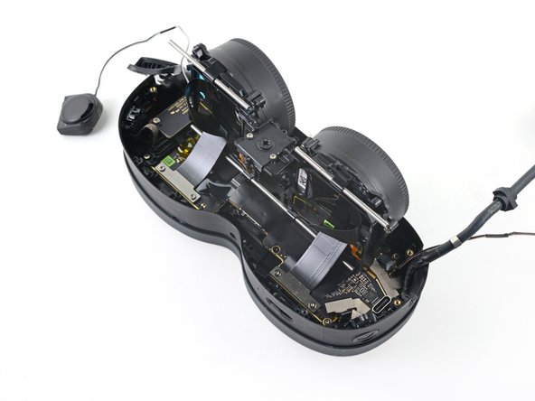
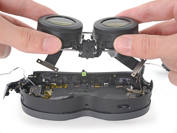
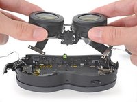
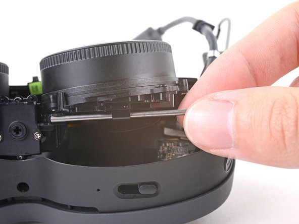
Lift the bottom of the lens assembly up to separate the bottom rails from their slots in the frame.
-
-
-
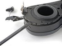
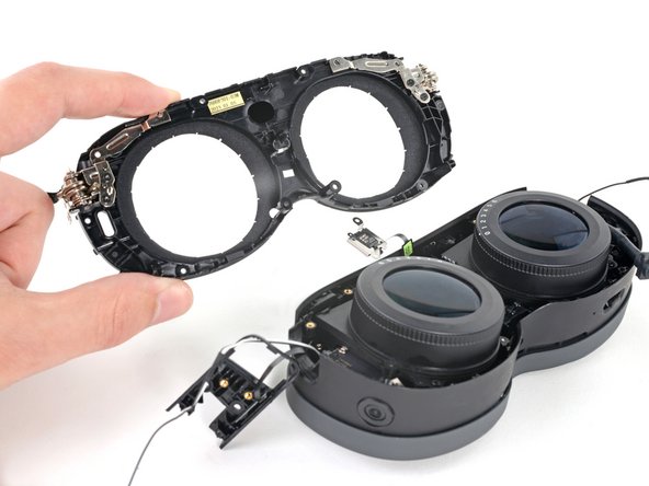
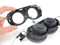
Pull the lens assembly upwards to separate the top rails from their slots in the frame.
-
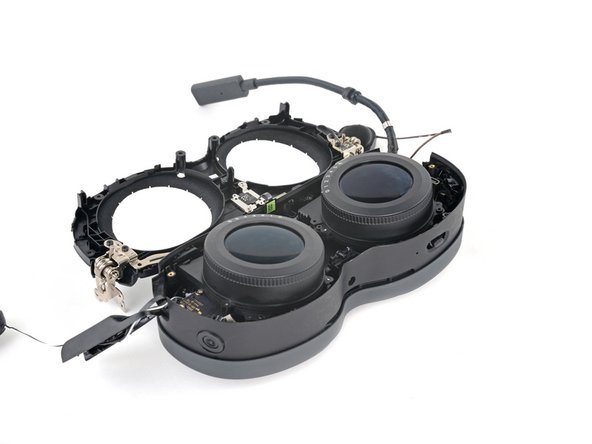
Rotate the lens assembly towards the top of the frame so it sits upright with its cable connectors exposed.
-
-
-
Use a T5 Torx screwdriver to remove the four 3.4 mm‑long screws securing the lens assembly cables.
-
-
-
Use the flat end of a spudger to pry up and disconnect the lens assembly cable connector.
-
Repeat this procedure for the other connector.
-
-
-
In order for the lens assembly to rest in the frame properly, it needs to align with a peg in the IPD (interpupillary distance) slider.
-
-
-
Slide the top left rail into its slot.
-
Align the other rails.
-
Press the lens assembly into place, making sure to realign the center peg.
-
-
In diesem Schritt verwendetes Werkzeug:Tweezers$4.99
-
Use tweezers to peel off the black tape covering the proximity sensor connector.
-
-
-
Use the point of a spudger to lift up the locking flap on the proximity sensor ZIF connector.
-
-
-
Use tweezers to pull the proximity sensor cable out of its slot in the motherboard.
-
-
-
Use a T5 Torx screwdriver to remove the two 3.4 mm‑long screws securing the motion sensor.
-
-
-
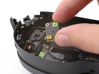
Lift the motion sensor off its pegs in the frame.
-
Flip over the motion sensor and lay it on the frame before continuing.
-
-
-
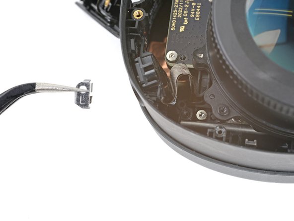
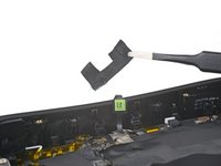
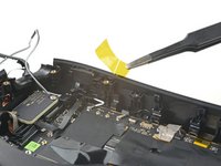
Peel off the yellow tape covering the motion sensor cable connector.
-
-
-
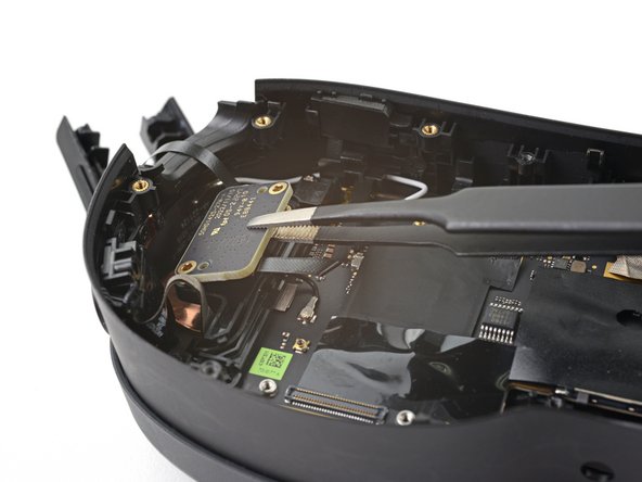
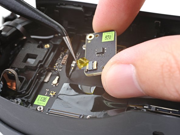
Use the point of a spudger to lift up the locking flap on the motion sensor ZIF connector.
-
-
In diesem Schritt verwendetes Werkzeug:Tweezers$4.99
-
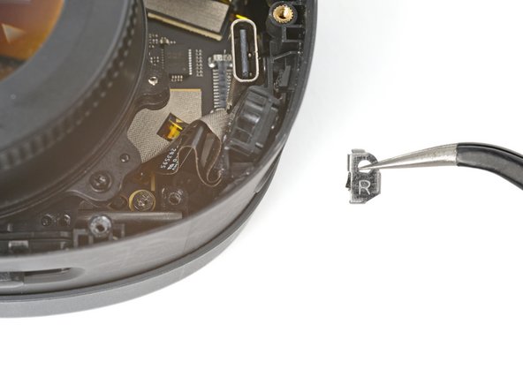
Use tweezers to pull the motion sensor cable connector out of its slot.
-
Remove the motion sensor.
-
-
In diesem Schritt verwendetes Werkzeug:Tweezers$4.99
-
Use tweezers to pull the right speaker connector out of its socket.
-
-
-
Use tweezers to pull the left speaker connector out of its socket.
-
-
-
Insert one arm of your tweezers between the volume button cable and the hinge cover.
-
Pry away from the hinge cover to separate the adhesive.
-
-
-
Use your tweezers to pull the volume button cable out of its slot in the hinge cover.
-
-
-
Use one arm of your tweezers to pry up and disconnect the bottom left antenna cable.
-
-
-
Use tweezers to guide the bottom left antenna cable out of its slot in the motion sensor bracket.
-
-
-
Use a T5 Torx screwdriver to remove the two 4.9 mm‑long screws securing the motion sensor bracket.
-
-
-
Lift the motion sensor off its pegs on the motherboard.
-
Remove the motion sensor bracket.
-
-
-
Use tweezers to peel back the gray conductive tape covering the left side‑camera ZIF connector.
-
-
-
Use tweezers to peel off the black tape covering the left side‑camera ZIF connector.
-
-
-
Use flat end of a spudger to lift up the locking flap on the left side‑camera ZIF connector.
-
-
-
Use tweezers to pull the left side‑camera cable connector out of its slot in the motherboard.
-
-
-
Use tweezers to peel back the gray conductive tape covering the left tracking camera ZIF connector.
-
-
-
Use tweezers to peel off the black tape covering the left tracking camera ZIF connector.
-
-
-
Use a spudger to lift up the locking flap on the left tracking camera ZIF connector.
-
-
-
Use tweezers to pull the left tracking camera cable connector out of its slot in the motherboard.
-
-
-
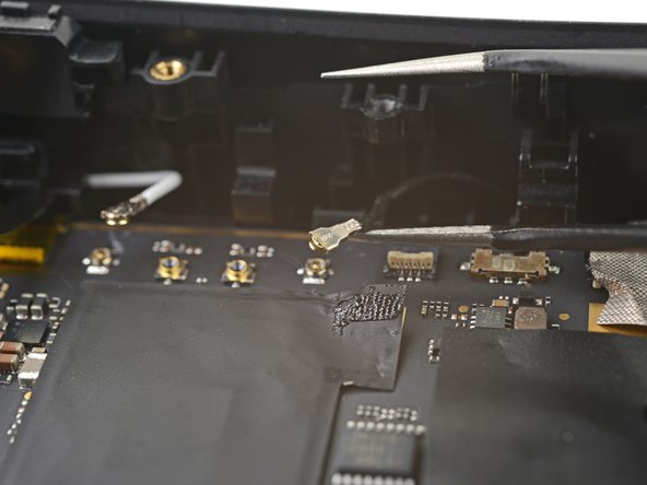
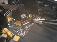
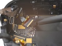
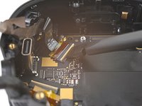
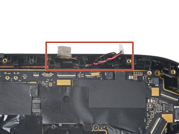
Use one arm of your tweezers to pry up and disconnect the top left white antenna cable.
-
Repeat for the top right black antenna cable.
-
-
-
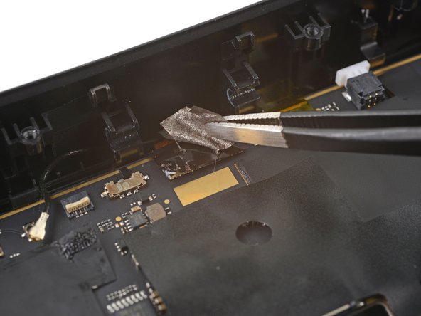
Use tweezers to peel back the gray conductive tape covering the pass-through camera ZIF connector.
-
-
-
Use tweezers to peel off the black tape covering the pass-through camera ZIF connector.
-
-
-
Use a spudger to lift up the locking flap on the pass-through camera ZIF connector.
-
-
-
Use tweezers to pull the pass-through camera cable connector out of its slot in the motherboard.
-
-
-
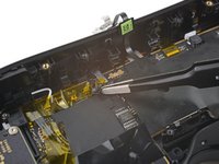
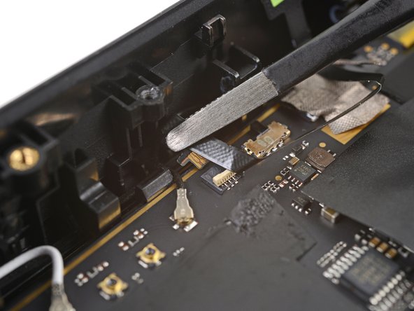
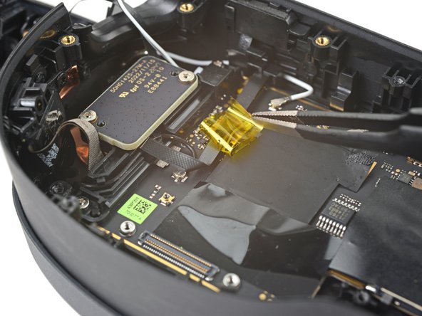
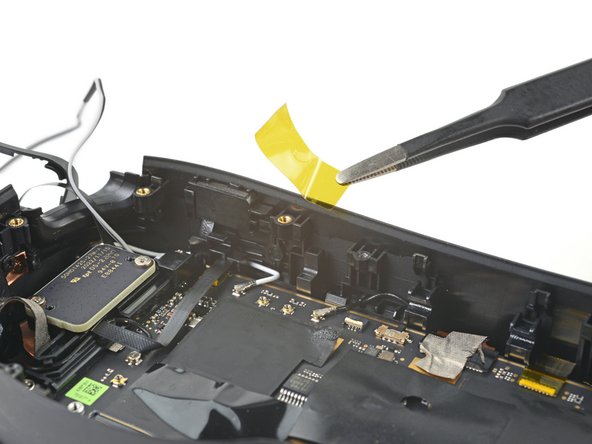
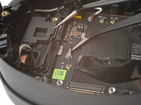
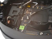
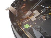
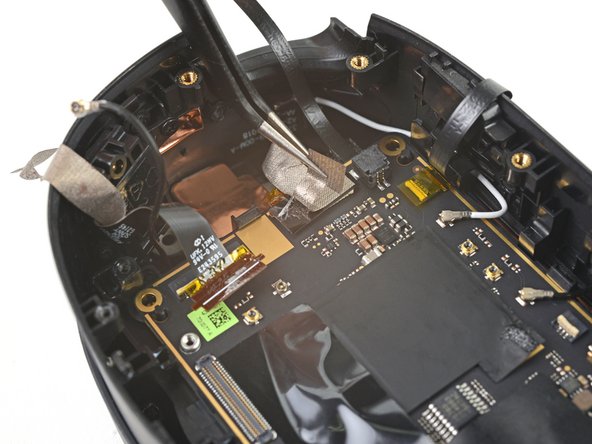
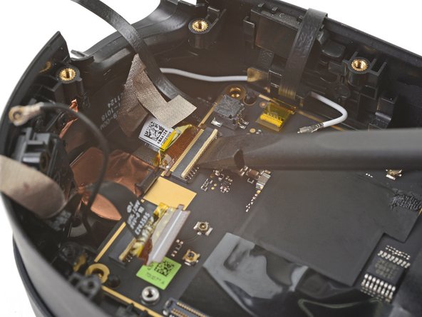
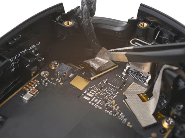
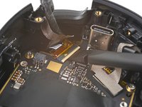
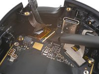
Use tweezers to peel off the yellow tape covering the microphone ZIF cable connector.
-
-
-
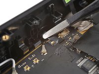
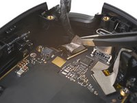
Use the point of a spudger to lift up the locking flap on the microphone ZIF connector.
-
-
-
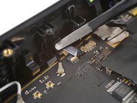
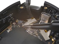
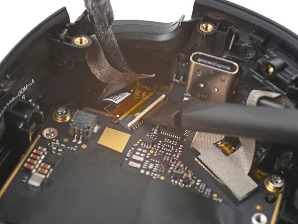
Use tweezers to pull the microphone cable connector out of its slot in the motherboard.
-
-
-
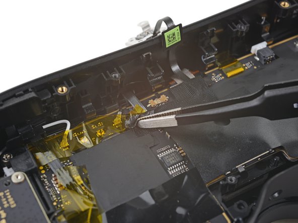
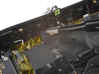
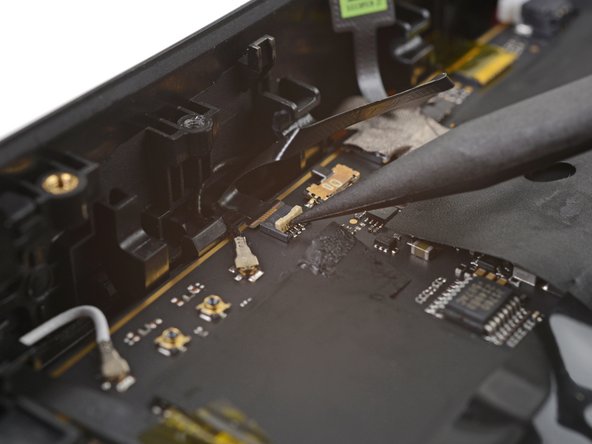
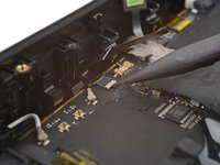
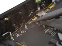
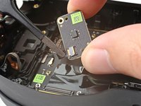
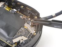
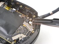
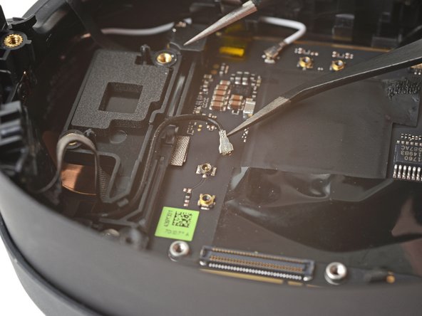
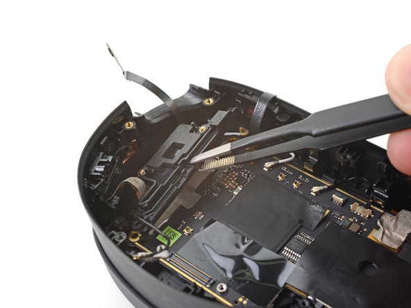
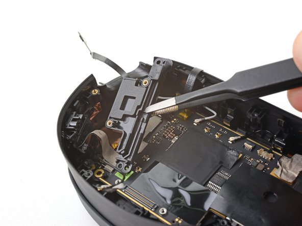
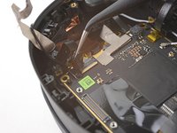
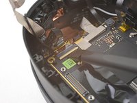
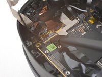
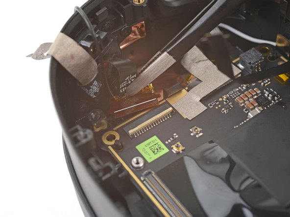
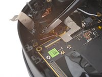
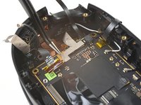
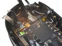
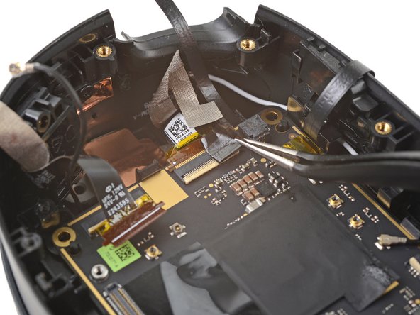
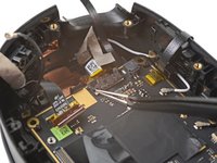
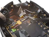
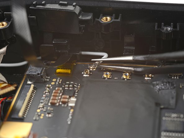
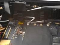
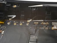
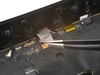
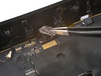
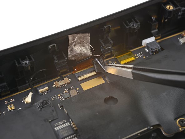
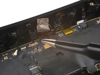
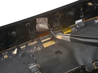
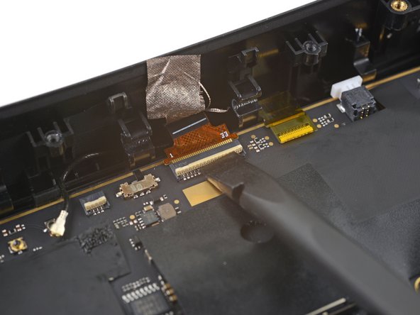
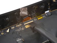
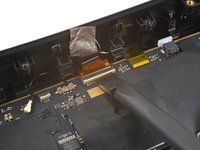
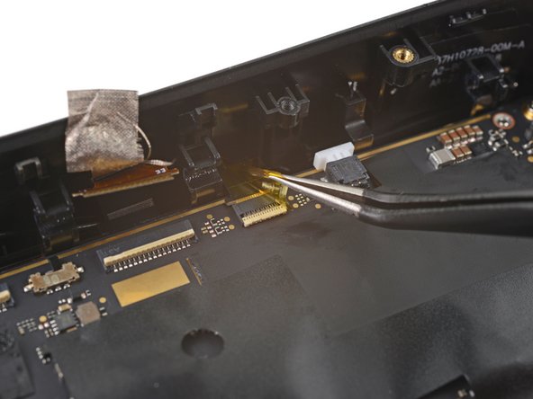
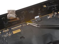
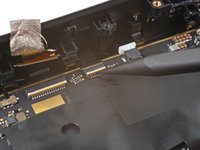
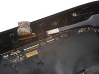
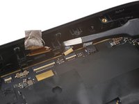
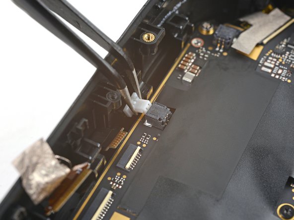
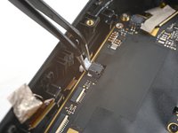
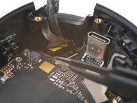
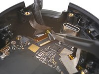
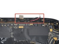
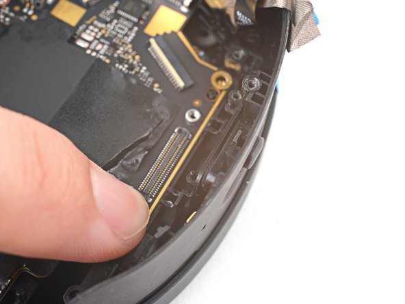
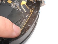
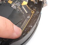
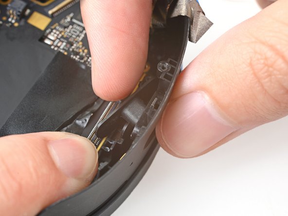
Use tweezers to pull the depth sensor cable connector out of its slot in the motherboard.
-
-
-
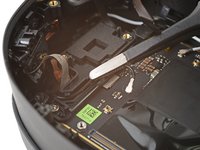
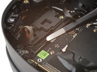
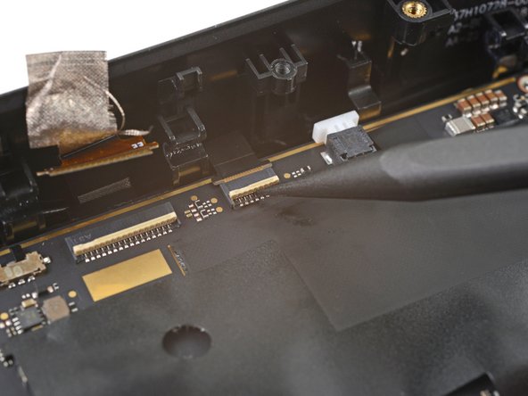
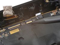
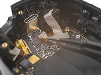
Use tweezers to peel back the gray conductive tape covering the right tracking camera ZIF connector.
-
-
-
Use tweezers to peel off the black tape covering the right tracking camera ZIF connector.
-
-
-
Use a spudger to lift up the locking flap on the right tracking camera ZIF connector.
-
-
-
Use tweezers to pull the right tracking camera cable connector out of its slot.
-
-
-
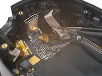
Use tweezers to peel back the gray conductive tape covering the right side‑camera ZIF connector.
-
-
-
Use tweezers to peel off the black tape covering the right side‑camera ZIF connector.
-
-
-
Use a spudger to lift up the locking flap on the right side-camera ZIF connector.
-
-
-
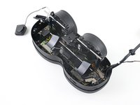
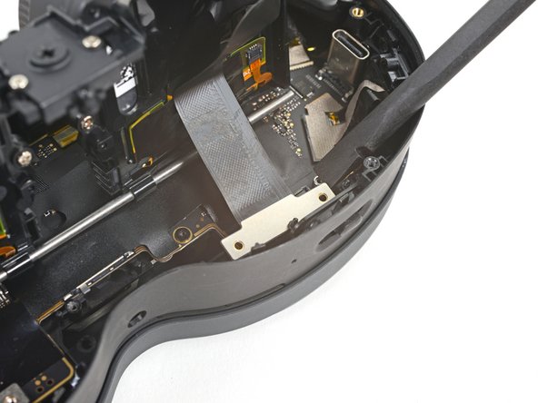
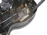
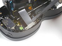
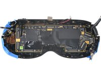
Use a T5 Torx screwdriver to remove the two 4.9 mm‑long screws securing the motherboard frame.
-
-
-
Use tape with light adhesive, such as painter's tape, to keep the left and right side cables away from the motherboard.
-
The cables near the top edge need slack for the motherboard to rest properly in the frame. Avoid taping them tightly—or avoid taping them altogether.
-
-
-
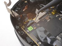
Lift the power button out of its slot in the frame.
-
-
-
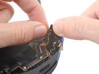
Press down the bottom right corner of the motherboard so its edge rests under the IPD slider.
-
-
-
While pressing down on the motherboard, push the IPD slider out of its slot in the frame.
-
Remove the IPD slider.
-
-
-
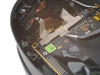
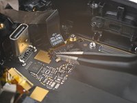
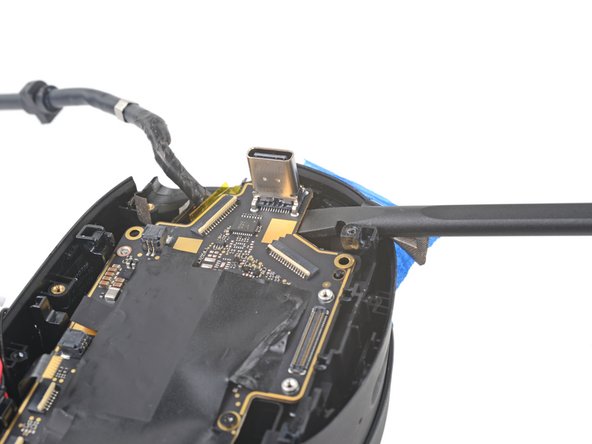
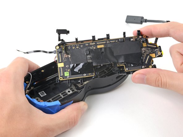
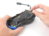
Grip the USB-C port with one hand and the right side of the frame with the other.
-
Pull the frame outward while lifting the motherboard assembly until it clears its slot next to the right side‑camera.
-
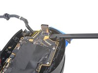
Use a spudger to pry up the motherboard assembly until its right side completely clears the frame.
-
-
-
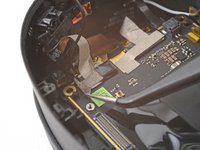
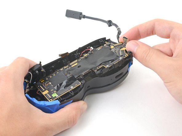
Pull the right side of the motherboard assembly toward the bottom edge of the device to separate it from the frame.
-
Remove the motherboard assembly.
-
-
-
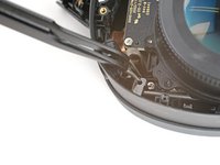
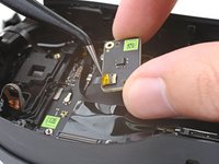
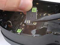
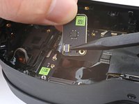
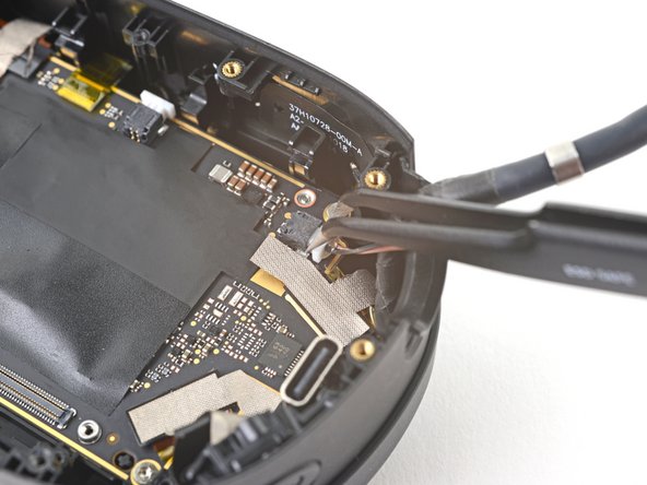
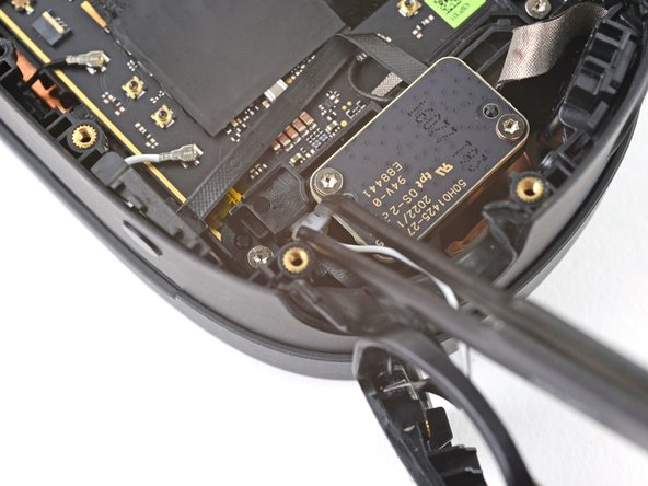
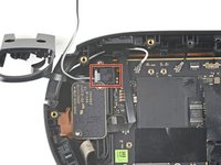
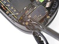
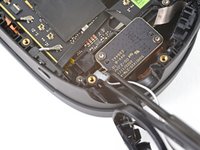
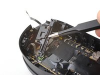
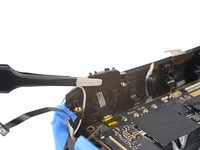
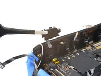
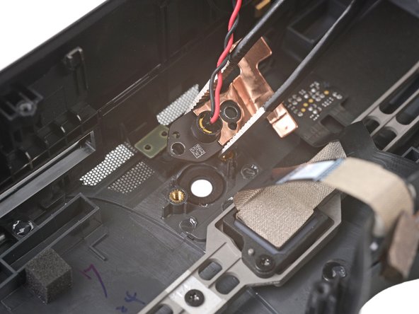
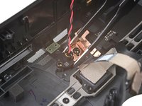
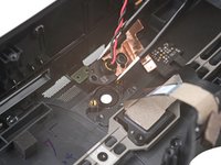
Use a T5 Torx screwdriver to remove the two 3.5 mm‑long screws securing the depth sensor.
-
-
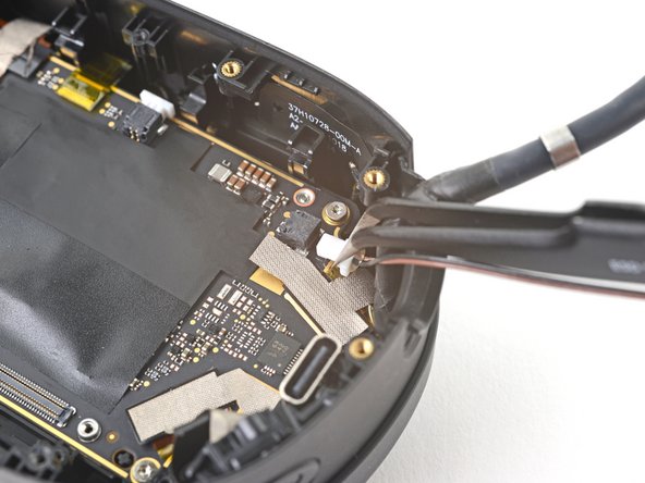
In diesem Schritt verwendetes Werkzeug:Tweezers$4.99
-
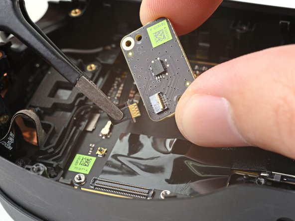
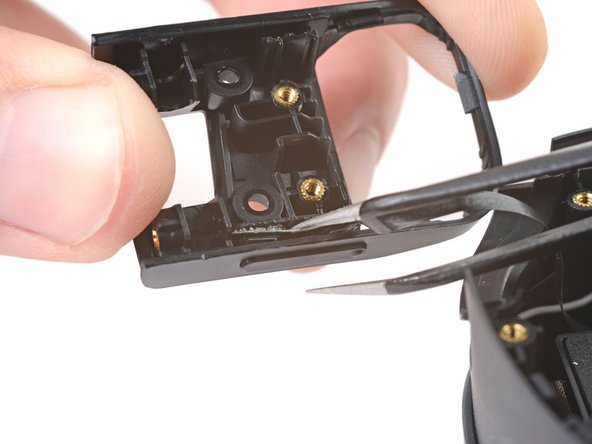
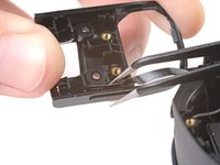
Use tweezers to pull the depth sensor off of its two alignment pegs in the frame.
-
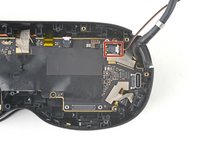
Remove the depth sensor.
-


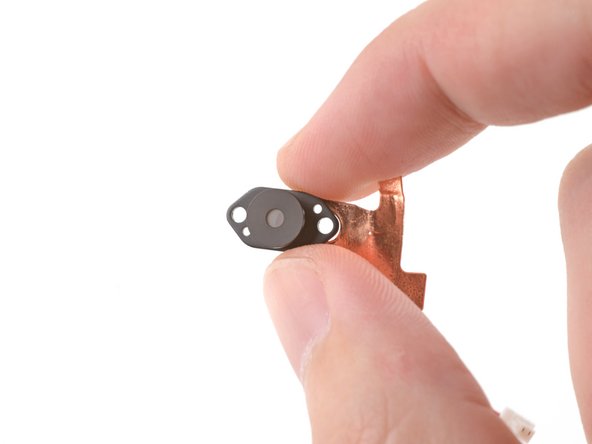

Compare your new replacement part to the original part—you may need to transfer remaining components or remove adhesive backings from the new part before installing.
To reassemble your device, follow these instructions in reverse order.
Take your e-waste to an R2 or e-Stewards certified recycler.
Repair didn’t go as planned? Try some basic troubleshooting, or ask our Answers Community for help.

