Einleitung
Der Austausch des Mikrofons erfordert den Ausbau des Logic Boards.
Was du brauchst
-
-
Entferne die zehn Schrauben, die das obere und das untere Gehäuse zusammenhalten.
-
Drei 13,5 mm (14,1 mm) Kreuzschlitzschrauben.
-
Sieben 3 mm Kreuzschlitzschrauben.
-
-
-
Hebe das Gehäuseunterteil nahe beim Lüfter mit beiden Händen an und löse es so von den beiden Clips, die es mit dem Gehäuseoberteil verbinden.
-
Entferne das Gehäuseunterteil und lege es zur Seite.
16 GB is the max
-
-
-
Benutze die Kante eines Spudgers, um den Akkustecker nach oben aus seinem Anschluss zu hebeln.
nails work pretty well as well...
At first sight I was confused when I read the description at this step, 'cause it seemed that disconnecting the battery connector was optional, in order to eliminate static discharge. While it's a helpful advice in other circumstances (as mentioned as an example changing hard drives), when changing the battery it is not an option - you have to disconnect the battery connector.
It would have been better to mention the optional disconnecting recommendation in a side-note.
Other than that, an excellent guide!
the fact that this step is optional can not be stressed enough. i tried disconnecting the battery and in the process it short circuited which now leaves me with an even more expensive problem than i had before when i just wanted to change hard drives (at least the new hard drive works fine..)
the hard drive changing worked though.
Any tool used to pry on the battery connector must be non metallic, to prevent unintentional short circuit between the connector pins. In my case, my index finger nails were strong enough.
Excellent guide, it was as easy as a breeze to replace my battery. I can't believe I nearly followed Apple in their saying that this part was not user replaceable. Great job for this description, and many thanks. iFixIt is THE reference for Mac owners.
Patrick.
So - I have a weird comment about this. I wanted to make sure that I was getting the right model - so I opened up my laptop and then thought "well, why not just remove the battery while i'm in here, it's shot anyway". Though, I forgot about the stupid screws (Apple really did us over on that one!). Though I disconnected the battery connector and didn't bother to re-connect it when I was finished and just put the cover back on.
Here's the weird part - when I went to turn my laptop back on...MY BATTERY WAS RECOGNIZED...AND WORKING! I was under the impression that the connector "connects" the battery's charge to the laptop, but this just doesn't make sense! Plus, now my very dead battery is in "normal" condition according to the system report. I haven't worked for apple, but have about 5 years of IT experience and am baffled by this! I'm starting to think i've experience a miracle! Has this happened to anyone else?
Possibly disconnecting the battery caused the System Management Controller to reset. That might have been your problem rather than the battery itself. See http://osxdaily.com/2010/03/24/when-and-...
I tried spudging the corner closer to the wires which was probably a bad idea. The corner broke off! I can't believe it was that brittle. So be careful. If it did it again, I'd aim for the corners AWAY from the wires or the sides themselves, though I seem to recall there not being much of a lip.
I used the spudger to gently ease the battery connector out. I then placed a q-tip between the connector and it’s socket to avoid making an accidental connection. A toothpick or some other soft stick might also work.
My battery connector had a shiny metal cover over it like a male USB plug. I had to take the 3 peace symbol screws oit and remove the battery before I could access thr plug properly. My battery plug also came off parallel to the board by walking the black plastic part off the metal part towards the battery. It required quite a bit of force to walk it off the connector. I broke a spudger trying. Something nonconductive but strong like a wittled down bamboo chopstick could work well.
Translate to Spanish:
Para ciertas reparaciones (por ejemplo, el disco duro), no es necesario desconectar el conector de la batería, pero evita cualquier cortocircuito accidental de la electrónica en la placa base. Si no desconecta el conector de la batería, tenga cuidado ya que partes de la placa base pueden estar electrificadas.
Use el borde de un spudger para levantar el conector de la batería hacia arriba desde su zócalo en la placa lógica.
Es útil hacer palanca hacia arriba en ambos lados cortos del conector para "sacarlo" de su zócalo.
The BATTERY MUST BE DISCONNECTED - it is NOT OPTIONAL if you are going to remove the logic board.
These instructions are for Removing The Logic Board, so if that is what you are going to do the battery MUST be disconnected.
The informational item beginning with the words “For certain repairs (e.g. hard drive), disconnecting the battery connector is not necessary … “ is NOT applicable to a set of instructions on removing a logic board and it should be deleted from this otherwise excellent set of instructions.
In my opinion the RAM should be removed first - i.e., before the battery is removed.
The RAM DIMMS are just in the way if they are left in their sockets on the logic board until step 33.
I cannot see any useful reason to not remove them very early in the sequence.
-
-
-
Biege das Akkukabel leicht von seinem Anschluss auf dem Logic Board weg, damit es sich nicht versehentlich wieder selbst verbindet, während du arbeitest.
My battery connect was like mid 2010 model
Why not go ahead and remove the battery at this point instead of bending the battery connector back (see steps 23 -25 below)?
Translate to Sanish: Doble el cable de la batería ligeramente lejos de su zócalo en la placa lógica para que no se conecte accidentalmente mientras trabaja.
-
-
-
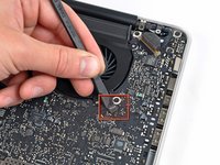
Entferne die drei 3,4 mm T6 Torx Schrauben, die den linken Ventilator am Logic Board befestigen.
Je vais juste vous surprendre car je suis français.
JI'll just surprise you because I am French .
I understood the problem of the left fan. In fact the problem is with the design at Apple. The fan housing is too narrow vertically a few tenths of millimeters. This is why so many problems . The left fans deteriorate very quickly.
The solution is very simple. Buy a new fan in China, it is the cheapest and level it's very fast delivery . Warning it comes fan already used but in good condition.
The thing to do is to over- raise the fan does not rub and deteriorating. To do so just buy a zinc washer 3 mm diameter available from my local hardware store ( € 3 for 70 pieces ) and place it under the black screw fully right and top right . The over- elevation leads to no longer have friction effect.
Thats ALL !!!
on my screwdriver set, the T6 screw driver felt wobbly. It felt like I would strip the screw if not careful. So I used a T7 screw driver, and it was much more snug.
Same here. T6 did not fit at all. Too small.
Bummer. Will have to screw my MBP back together and get a T7 on Monday…
-
-
-
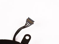
Verwende das flache Ende eines Spudgers, um den Verbinder des linken Ventilators vom Logic Board zu lösen
I successfully removed my right fan, cleaned it and installed it back. But when it came to the left one I accidentally broke the connector from the logic board. Now I'm left with only one functioning fan. I'm using an external laptop fan. Do I have to replace the whole logic board or can it be fixed somehow? My temp is between 90-95 C when I run a heavy game.
In case anyone else accidentally breaks a fan connector, check the comment on step #14. It is basically the same connection, so that should work here.
Relevant part of comment - “To replace it, I removed the socket, held it in place against the solder pads and ran a 750degF soldering iron across the pads. It's definitely reattached it, I'm not sure how good the electrical contacts are yet.”
-
-
-
Hebe den linken Ventilator aus dem oberen Gehäuse.
If you’re just looking to remove fluff that can block the fan outlets, you don’t need to disconnect fan power connector from the logic board header (Step 6) - the fans on my MacBook Pro kept spinning up to max speed (6200rpm) so I removed the three T6 Torx screws (Step 5) and carefully lifted the fan to oneside removed the fluff with a toothpick and replaced the fan and screws — repeated this for both left and right fans
-
-
-
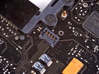
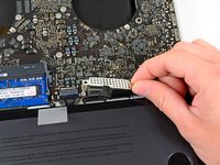
Hebe mit dem flachen Ende eines Spudgers den Verbinder des rechten Ventilators aus seinem Sockel auf dem Logic Board.
Of course, this is not the right fan but the left in the picture.
-
-
-
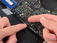
Entferne die drei 3,4 mm (3,1 mm) Torx T6 Schrauben, die den rechten Ventilator am Logic Board befestigen.
-
Hebe den rechten Ventilator aus seiner Öffnung im Logic Board.
After doing this remove the iSight connection; it’s the thin strip located at the bottom of the speaker socket. You can carefully pull it out.
-
-
-
-
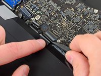
Ziehe das Kamerakabel aus seinem Sockel auf dem Logic Board.
One can see how to remove the cable in this picture: https://d3nevzfk7ii3be.cloudfront.net/ig...
Better than pull is to push it with something like a screwdrive at the small angle left and right.
Before doing this remove the iSight connection; it’s the thin strip located at the bottom of the speaker socket. You can carefully pull it out.
-
-
-
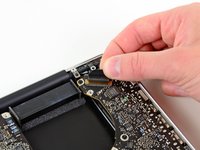
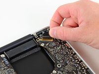
Hebe den Airport/Bluetooth Verbinder mit dem flachen Ende des Spudgers aus seinem Sockel auf dem Logic Board.
Am I the only one but my MacBook has black shielding on the CD-R drive, not some clear tape stuff to reveal the internals on the drive….
-
-
-
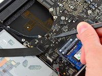
Hebe den Verbinder zum optischen Laufwerk mit dem flachen Ende des Spudgers aus seinem Sockel auf dem Logic Board.
Mine had a little adhesive strip behind the connector. Pull gently
Also had an adhesive strip, thanks for mentioning it!
-
-
-
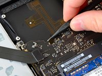
Löse das Kabel zur Festplatte/IR Sensor aus seinem Sockel auf dem Logic Board, indem du unter dem Verbinder anhebst.
-
-
-
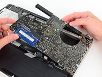
Hebe den Verbinder des Subwoofers/rechten Lautsprechers aus seinem Sockel auf dem Logic Board.
Be really, really careful detaching this connector - make sure it's lifted from the cable side. I managed to remove the whole lot from the logic board by accident. On mine it was disguised under a lump of rubber foam.
To replace it, I removed the socket, held it in place against the solder pads and ran a 750degF soldering iron across the pads. It's definitely reattached it, I'm not sure how good the electrical contacts are yet.
There is foam on the top of this connector. Do not pry up from under that. Instead, put your spudger underneath the red and black wires themselves and pry up. Very little resistance.
Passe auf, nicht den Plastikanschluss des Lautsprechers vom Logic Board abzubrechen, wenn du den Stecker mit einem Spudger gerade nach oben und aus dem Anschluss hebst!
-
-
-
Die Abdeckung über dem Tastatur/Trackpadkabel ist mit zwei 1,5 mm (1,2 mm) Kreuzschlitzschrauben auf dem Logic Board befestigt. Drehe sie heraus.
-
Hebe die Abdeckung ab und lege sie zur Seite.
I ended up using a #000 phillips screwdriver instead of the #00. I was able to get this piece up without issue.
Can I get it work with PH#00?
I was able to skip this step, along with 16, 17, & 18, and complete the repair successfully. Instead of fully removing the logic board as described in step 22, I lifted the left edge and then wiggled it left until I could lift it from the hinge edge; this gave me plenty of room to see what I was doing while removing and replacing the DC-in board.
@Sarah Dunlap. Yes, I did the same, it entirely possible ( although fiddly ) to complete this repair without fully removing the Logic board and instead lifting it out of the way taking care not to put too much tension on the keyboard ribbon cable.
I used the J000 bit (I think this is a JIS bit, not Phillips) for these screws and they seemed like a much better fit. It seems like the screws aren’t actually Phillips (ie. with the curved, cam-out corners) but are squared off.
On mine the small black piece of plastic directly south of the plate we just removed that is connected to the aluminum frame underneath by two screws was broken in the middle. Can’t find what this piece is called or what its purpose is. It swings open from the screws like a door because it is broken in the middle but it doesn’t seem to have intrinsic value other than filling up space and seems that it would be held in place by the battery and the plate and the logic board once assembled.
I ended stripping one of the screws with Phillips #00 and just bent the metal piece carefully up instead so I could disconnect the two connectors underneath it. These screws are awful!
Aaron. The small black piece of plastic is one of two clips. The other is to the left of the one you mention. On the inside of the bottom case there are two small metal tabs that slip into these two black plastic clips.
As a couple of others have mentioned (above), I too had trouble getting these two screws out too. My problem was that they had corroded and locked into their threaded sockets. Also, the corrosion had rotted out the inside shape of the Phillips slots so that no screwdriver would fit properly.
I had to cut the cover down the middle and bend it up and out of the way.
Hey I’m trying to find the screws for this step online through ebay or amazon. But I can’t find it.
Is the screws the same as the one used on the trackpad, or the keyboard (ebay selling 100 pieces set)?
Can anyone check?
-
-
-
Heble den Verbinder zum Trackpad mit dem flachen Ende des Spudgers aus seinem Sockel auf dem Logic Board.
-
-
-
Klappe die Halteklappe des ZIF Verbinders des Tastaturflachbandkabels mit dem Fingernagel hoch.
-
Löse das Flachbandkabel der Tastatur mit der Spitze des Spudgers aus seinem Sockel.
Need a better picture of the zif connector. You lift the lock from the side farthest from the flat cable, and it lifts toward the cable. When reinserting be sure to get the cable all the way or you may have only half the keyboard working.
Definitely should have read this comment before I cracked the ZIF socket…
this almost trigger panic button in my head, since after reassembly, my macbook wont turn on at all. turned out the keyboard zif cable is not fully inserted to the socket, and since power button is also connected through those flex, its no wonder it wont respond when i press it. Re-seat the zif flex and everything went great.
I could use some advice on reinserting the ZIF cable firmly in its socket. I can get it started, but getting it far enough in to make contact is difficult, given its flexibility. Any tips on manipulating it?
I used a piece of sticky tape that I attached to the ZIF cable, then pulled firmly on the tape (attached to the cable) to get the ZIF cable to seat properly. The tape held to the cable, the ZIF cable seated properly, and the keyboard worked.
REINSERTING THIS CABLE WAS ABSOLUTELY THE MOST DIFFICULT STEP IN THIS WHOLE PROCESS!
Key points:
•Make sure that it's inserted evenly. It's tempting to get one edge in, and then the other, but that approach will prevent it from seating properly.
•The cable goes all the way in. There is maybe 1/16" of the little grooves showing, but not much more.
•Once the cable is properly seated, use a piece of tape to pull it all the way in, and keep the tension on the tape as you use a sprudger to flip down the retaining flap.
•It's a fragile connection, and if you break the cable it's a top-case or keyboard replacement, which is either expensive or a PITA, so patience is key.
It's very easy to do this step incorrectly. Make sure to use your fingernail and pry gently. This was the only step I felt didn't have a great explanation and damaging the part could easily happen.
I messed up and broke the connector. Here is part of a video showing in close-up how to remove it properly (different model Mac, same connector). Wish I had seen it before I tried it.
Thank you for posting that video link. You saved me a lot of frustration!
Thanks for posting the video. Made it much clearer how to disconnect and save damage!
When they say "retaining flap", they are referring to a square plastic clip that hinges to the clip on the board. Starts at 7:15 in the video.
Thanks a lot! Great video
I needed that video. Thanks
Veeerrrry subtle. This video saved me I think. Thank you!
The key is between 7:33 and 7:36 but I didn’t catch it until the third watch.
Aaron -
Thank you to everyone who commented about this step. I did not have any trouble doing this but I could have. Also for all the excellent clarification especially the tips on reinserting the ribbon cable which I have yet to do after I hopefully fix the logic board
When they say "pull" the cable, they mean to "slide" it. Do not lift and pull.
Attaching a small piece of tape and pulling parallel to motherboard did the trick.
I acquired a macbook pro with a cut trackpad wire and no battery. In looking at this layout my concern is… what if the connection is pulled from the hinge and the hinge to hold it into place is completely missing?
The comment Kal left about lifting the retaining flap is key during reassembly!
I, too, totally missed that there is a plastic “bar” covering the end of the pins. Without that lifted up, it’s %#*@ near impossible to push the connector in since the flap/bar is putting pressure downwards.
With the retaining flap down, it comes out without too much effort. But putting it back in is a whole different story. Be sure to lift it up!
For reinserting, just be patient, lining up the ribbon, keeping a good hold on the tab, and applying even pressure along the ribbon, slowly, firmly reinserting. If the power button doesn’t work when you put everything back together, you will know the ribbon needs better connection. I promise you can do it!
ps, donʻt forget to LATCH the retaining flap back in place. i forgot and had to re-open the computer, was only getting the letter “H”. wasted 5 minutes for a 2 second slip up.
Thanks for this priceless comment. Had 8 dead keys. It occurred to me to check the comments here and, lo and behold, same here! Who needs adventure sports or drug taking for highs and lows.
Rob -
-
-
-
Löse den Verbinder der Akkuanzeige mit dem flachen Ende des Spudgers aus seinem Sockel auf dem Logic Board.
It is not obvious which direction to pull. I pulled towards towards the center and pulled off the sponge handle. Easy to put back on. Pull towards the nearest corner.
-
-
-
Fasse die Zuglasche aus Kunststoff, die an der Sicherung des Displaykabels befestigt ist, und drehe sie in Richtung der Seite mit der Stromeingangsbuchse am Computer.
-
Ziehe das Displaykabel aus seinem Sockel auf dem Logic Board.
The metallic flap controlled by the plastic handle looks like it could easily break... a safer route is to grab the shielded cable after rotating the metal flap out of socket and gently pry it out of the socket by applying force parallel to the logic board. It will probably take a few minutes but you could save yourself some gray hairs.
This is the hardest step IMO
"Pull the cable straight" means to slide the connector out, do not lift and pull. Also, check for a square locking clip attached to the plug, if it won't come out.
I really advise you to remove the cable retainer (one 8.6 phillips, you can see a photo in the display replacement tutorial) BEFORE unplugging the cable, to have more freedom of movement (to plug it in back it's even more important). Those are REALLY flimsy (i just broke one without being brutal and believe me you don't want to change it).
I found it helpful to remove the bracket for the display cable to allow more movement of the cable when attempting to reassemble
Really great site!! replaced a LB in an mid 2010 MBP with kernal panic crash. Fixed! No issues with detailed procedure and comments. So I'll add one for this step. This was the simplest step really. Additional clues. (Wish I could post a pix). Look at the gold conn in the pix above. Note that the cable mates with the conn with the 2 tabs each side showing full insertion. The silver retainer pops up, bar away from the cable. Using my custom tool, a small screw driver, filed really small as I don't have a #000 Phillips, release the retainer, then carefully wedge open the tab on each side, inserting your "tool" in the slot. Neatly and slowly, the conn comes apart. Putting it back together, once the conn is alligned, just push alternately on each tab. Doesn't take much effort, better that pushing on the cable. I also appreciate the comment that removing the clamp, both clamps with one screw actually, makes this easier.
This made a difference for me. I put my arm behind the computer to pull the hinge and tape everything away from me out of my way and holding out with my thumb and walk each side and bit by bit using the tool. I’ll add be very careful that it is steady parallel force. Also if you can’t get the hinge clip down when the cable seems in try steady flat force across the clip of the hinge with the tool alternating with walking it in even more with your thumb on top holding it down so you don’t actually accidentally pry anything perpendicularly up.
Aaron -
This is indeed a tricky step. First time, after following all the steps and reassembling I had no screen, which freaked me out. Luckily, another go at the connector did the trick and now I’m a happy owner of a macbook with a new trackpad. Thanks!
This step is really unclear! After grabbing what I thought was the “plastic pull tab” and having it come off in my hand, I was clueless about how to proceed. After puzzling over it for about 15 minutes, I saw the actual “plastic pull tab”, which was against the mother board near the fan. Pulling this upward unlocked the metal hinge and everything else was obvious after that.
I agree, this step was unclear. Part of the problem may be variations between logic boards. Mine did not look like the one pictured here. Mine has a tab lying flat against the logic board, as also described by xtophr. If this describes yours, check out [|this video] https://m.youtube.com/watch?v=-IE3WNOsrZ... (around 40 seconds in) to see exactly how it comes out. You lift the locking clip up by the plastic tab, then (with a little bit of downward pressure on the cable) slide it out towards the nearest corner of the machine.
Wow Thansks for the video link. That definetly helped out to understand how this part actually moves. It is pretty easy after this explanation
ummm, yeah, this was an intimidating 2-STEP step. sounds easy, lift the latch then pull back on the cable connector, but it took me several minutes (felt like an hour) to figure it out.. reinserting was worse, i couldnʻt figure out how to relatch the connection, lots of attempts, and i finally got it in. tested it gingerly, and i think itʻs ok. at least, the screen is working, so iʻll take that as a good sign.
Fortunately, the step was easy for me thanks to all the great comments above. It could have been a disaster otherwise.
Step 19 :
First remove the cable clamp, one screw in center behind the connector. Lift the plastic tab upwards and rotating back over the connector. Slide connector out by pulling gently on bend in the wire harness. To reconnect, slide connector into place by pushing on back of bend in wire harness, do not push hard. Use small flat blade at each corner to make final connection. Swing locking hinge down. Reinstall cable clamp.
I had a 2011 fully speced, Macbook pro 15 and for one day it died in like late 2017, I had asked a repair shop and they said dead GPU but looking at the gpu now I see no damage and also even if it was dead the CPUs internal graphics would allow it to boot anyway. Can someone help me?
-
-
-
Klappe die Halteklappe am ZIF Anschluss des Flachbandkabels der Tastaturbeleuchtung mit der Spitze des Spudgers hoch.
-
Ziehe das Flachbandkabel der Tastaturbeleuchtung aus seinem Sockel.
Connector slides out, do not lift and pull.
any replacement parts available for this? I pulled up instead of sliding cable :(
This step would benefit from a macro view of hinged retaining flap and clarification. The instruction about flipping up the hinged retaining flap is misleading people into trying to flip out the ribbon.
Another great save by good comments. Thank you, thank you. :)
-
-
-
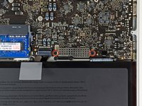
Drehe folgende neun Schrauben heraus:
-
Sieben 3,4 mm (3,1 mm) T6 Torx Schrauben auf dem Logic Board
-
Zwei 8 mm T6 Torx Schrauben auf dem DC-In Board
Remove T6 (smaller) screws first, that was the last screwdriver that you used (for smooth workflow).
Getting the DC board back in required a non-trivial amount of force to get it into position and lined up with the screw holes. It seemed to want to sit away further from it’s hole in the external case than it had to be to line up. I eventually got it in by leaving the main logic board out of it’s final position (but with the cable connected), which allowed me to get the leverage to push the DC board in so it would line up and be screwed in. Once it was in, I then positioned the main logic board and screwed it in.
-
-
-
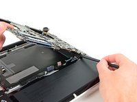
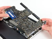
Hebe die ganze Einheit mit dem Logic Board vorsichtig auf der linken Seite an und aus dem Gehäuse heraus. Achte dabei darauf, dass sich das Kabel des optischen Laufwerks und die I/O Ports nicht verfangen.
-
Trenne falls nötig das Mikrofon mit dem flachen Ende des Spudgers vom oberen Gehäuse.
-
Ziehe die Seite des Logic Boards mit den I/O Ports seitlich vom Gehäuse weg und entferne die ganze Logic Board Einheit.
I had a little difficulty pulling the motherboard before the battery. I'm not sure why you would want to do it in the order listed here, but doing steps 23 and 24 first helped the board come out easier.
The thing that caught me on this step was that, at least on mine, the speaker box was glued/taped to the case, and so I got rather nervous trying to remove the logic board as it wouldn't move until said adhesive was pried apart. Thank goodness I knew the difference between the sounds of "board breaking" and "adhesive separating", but this step was still rather harrowing for me.
The microphone cable was easy to pry off the logic board for disassembly. For re-assembly, I was having a heck of a time getting the connector to connect to the logic board. There just isn't enough room to get your hands and tools in there and still see what you're doing (unless you're a dentist and you're used to that kind of thing). Anyway, I finally got brave and pulled the round, rubberized microphone from the case. I connected the short cable to the logic board, set the microphone in the made-for-the-microphone housing on the logic board, hoping it would stick itself back to the case once the logic board was in position, and I was back in business. In this case, simply stating "reverse these steps for reassembly" wasn't very forthcoming.
Pulling the microphone off the case is key to reassembling. Place the mic back into the cut-away in the speaker housing and plug the connection into the backside of the logic board
thx graciaaaas :)
When I did this step the microphone was REALLY STUCK to the upper case, it actually stayed stuck to it and disconnect "itself" from the mother board while I was lifting up everything.
Finally, there was no damage : I separated the microphone from the upper case while reassembling, then connected it back to the mother board and put it on its housing.
Count the number of connectors as you remove the board, so that when you put it back one does not get lost under the board and you can't figure out why it won't go in. You should do this.
If you laptop was getting hot when charging then be extra careful in this step because the foam pad under the logic board my have started to fuse to the casing. If the pad seems stuck then use a knife to gently pry it up.
I have the same case with Joseph Sikorski - it's hard to pull out the mother board because the speaker is glued that I thought their are remaining screws that hook in to it. Better use flat spudger to pry the right side that is stuck when you pull the left upward first.
Repairing a friend’s laptop… I wonder if the “glue” between the speaker and case is actually juice or soda, lol
This part was highly stressful. The microphone/left speaker assembly are fused to the underside of the logic board. As you are facing the project according to the layout in these photos, the mike assembly is on the right side of the logic board, towards the top end. It is fused to the logic board but it also has adhesive sticking it to the upper case. As you lift, you have to insert a long spudger flat end down into that corner and move it back and forth between the mike assembly and the upper case, and it will release. Be very patient, focused, and slow. The spare part I bought from iFixIt had an extra speaker there in case I messed up, but I did not need it.
Hallelujah! There is a God!…Been sitting here for the past 2 hours, eyeballing the rubber whatever it is ”My New Moto”..When I’m stuck…”READ THE COMMENTS!…Thanks to all of you!!!!
For reinserting the logic board, it helps to have a second person helping hold connection points to the side so you do not accidentally lay the logic board on top. Just go slowly, being mindful of all connections. (best to start by properly seating the DC power unit in the upper right corner)
This step need a better picture of how the speaker and microphone looked from beneath the board, so people can understand where they should pry with the stick tool to wiggle the adhesive. In my case, it was the microphone that stucked, luckily the connector of the mic itself wigle off when i pull the board sideway. N fortunately the connector wasnt torned.
For any of you have difficulty in this step i would suggest to actually disconnect the socket of the mic from the board first, and then only pull the mic itself from the upper case.
When you put in back, remember there’s 11 connectors-wires
-
-
My microphone was firmly seated in the speaker and came awayeasily when the logic board was lifted. When I wanted to remove the mic from the speaker it was resistant so I used the spudger and disconnected both the mic and the speaker from the logic board. Then, having the entire unit in hand I was able to gently pry the mic out of the speaker with the point of the spudger just under the wires.
-
-
Entferne die beiden 5 mm Kreuzschlitzschrauben, welche den linken Lautsprecher am Logic Board befestigen.
-
-
-
Ziehe vorsichtig die Kabel des linken Lautsprechers nach oben, um den Stecker des linken Lautsprechers aus seinem Sockel auf dem Logic Board zu heben.
-
-
-
Ziehe vorsichtig die Mikrofonkabel nach oben, um den Mikrofonstecker aus seinem Sockel auf dem Logic Board zu heben.
-


Um dein Gerät wieder zusammenzusetzen, folge den Schritten in umgekehrter Reihenfolge.
Um dein Gerät wieder zusammenzusetzen, folge den Schritten in umgekehrter Reihenfolge.
Rückgängig: Ich habe diese Anleitung nicht absolviert.
5 weitere Personen haben diese Anleitung absolviert.
Besonderer Dank geht an diese Übersetzer:innen:
100%

Diese Übersetzer:innen helfen uns, die Welt zu reparieren! Wie kann ich mithelfen?
Hier starten ›

Step 1 (technically step 9 - replacing the base plate) Apparently one of my screws was a micron or two smaller than the others. This screw belongs to the hole above the optical drive, which is also apparently a couple of microns smaller than the others. It took seven attempts to figure which screw had originally been in that hole; all the other screws were too large, but fitted perfectly everywhere else.
Bizarre much?
Will - Antwort
It might be a matter of how the screws are driven in, and not that they're slightly different sizes. When I reassembled my MacBook, a couple of the screws, including the one over the optical drive you mention, were hard to drive in and jutted up a little bit instead of sitting entirely flush. Swapping screws didn't help. The solution was to unscrew them and drive them in at a bit of an angle - perpendicular to the slightly curved surface of the back plate where the screw holes were, instead of fully vertical with respect to the ground the Macbook is sitting on. Doing it that way, the screws were easier to drive in and they all ended up flush in their holes. Didn't matter which screws they were. (I swapped a few around just to check after reading this.)
Andrew Janke -
I had no such screw issues. Either there are differences in manufacturing lots or I just got incredibly lucky during reassembly!
xtophr -
I discovered a great way of organizing the screws. I used an ice cube tray and added the screws in order, keeping the different kinds together. So when it came to reversing the steps, the screw order was an added control step to returning everything in its place.
leonie - Antwort
Great advise! Love it! :)
Ririds -
I used to do that and that worked really great until I bumped it by accident and the entire tray went on the rug! I spent the next day sorting things out.
Now I use these:
http://www.sciplus.com/p/50-114-CLEAR-PL...
The lower ones 50 to a package. I mark them w/ blue tape. Often if it's part like the fans, or the optical drive I'll tape the screws into/near the holes where they belong. I did this a lot especially w/ the bottom screws from MBPs until I'd done so many I knew exactly where the longer ones went.
Richard Sato -
I wrapped the screws in a piece of blue masking tape and wrote the number on the little pouch I made. Then I stuck the blue tape pouches on the underside of the case bottom in order.
Roscoe -
I take double-sided tape, put that on a piece of paper, stick the crews to that, and label them.
jelimoore -
Best I've found is a bead sorting tray. They're like $5 at Wal-Mart and they have a lid that seals up and won't let them jump between containers.
maccentric -
I take a sheet of paper, pierce the screws through the paper, take a pen and box the screws and write out what step they belong to.
Nils -
@Will, in my case I had the same result as you did. As a reminder to myself the next time I need to open the computer, I put a dot of white paint on those two screw's head and a very, very thin ring of white on the very edge of each hole, that way I'll know they go into those two holes.
Roger - Antwort
Actually the four screws on the bottom were not threaded all the way up. I didn't check to see if the thread gauge was the same on them, but it wasn't until I had about four screws out (I didn't take them out in the order that the bottom all came out first) that I noticed a difference. I then took out the rest of the bottom ones to see if they matched the two that were already out that weren't threaded to the top. They did. So I went under the assumption that those were all bottom screws and when I put it back together everything went fine with no resistance.
So there are three types of screws: Four for the bottom, three long ones as indicated and three others that might be slightly smaller than the bottom ones.
wresnick - Antwort
Hi,
Although its more than a year since your contribution, I thought you might be amused to know that it is not just that the screws go in more easily when at an angle, Apple actually drilled and tapped the holes at a 15% angle. I too had tried to drive them in straight. An Apple "genius" - I was in for something else - clarified the design for me. It was done so that the screws lay flush on the angled part of the lower case. Nice design, but since Apple encourages DIY memory and drive changes, they could have mentioned this little ... trap.
H Stahl -
MacBookPro8,2
Intel Core i7, 2,2 GHz, RAM 16 GB
Mountain Lion
May someone help me?
I have installed the second drive with ssd 840 evo, but when I try to copy the file from the new drive to the main hd this in not allowed (errore -36)
Piero - Antwort
To my knowledge you can't transfer a single file more than 4gb. I advise compressing to a bunch of rars to split the file size and moving them individually
1982sketcher -
Hey everyone, here's the very best way to PERFECTLY organize your screws AND keep track of the order of the procedure: Get a piece of plain corrugated cardboard and a pen (I like using a Sharpie). For EACH step of the disassembly, draw a simple diagram of the layout of the computer on the piece of cardboard, with dots or Xs where the screws are located. Right after you remove each screw from the computer, poke a hole in the cardboard in its corresponding diagram position with your screwdriver and place the screw in that hole. If there are other non-screw related parts to be removed, you can add notes below each step diagram to remind you of where they go or how they should be placed. This cardboard method is great not only because your screws will not go flying or get mixed up by accident if bumped, but each screw goes EXACTLY back where it came from and you can keep the cardboard as a template for future use if necessary!
- zerø K
zeroK - Antwort
a video of these steps
https://www.youtube.com/watch?v=SS9is40C...
julie56 - Antwort
These instructions worked great for me. I ordered a replacement battery from Key Power (on Amazon) for my 15" Macbook Pro (mid-2010). Cost was $74 shipped.
Battery came with 3 different screwdrivers to help with installation. I just needed the one size though, since my 2010 seemed to use all the same size screws.
Thanks!
Marcos - Antwort
During re-assembling (put the screws back in), it is important to note that the 3mm threaded holes are not completely vertical, but bent a little bit such that the hole direction is rectangular to the tapered surface. The force of the screwdriver must point towards the direction of the hole. Otherwise the screw gets jammed
kusi - Antwort
There is a FOOLPROOF WAY TO ORGANIZE ALL SCREWS and other parts removed.
Print the repair guide.
Yes, the actual photo of the bottom of the laptop with the circles around the screws.
When you remove the screw, tape it to the photograph.
You will tape the screw to the exact location that you just removed it from.
Same thing with any part you remove.
splashzoneent - Antwort
Thanks Splash!!! I used your suggested method, and it was perfect: kept all my screws, and i was able to, very easily, put them back in their correct place. I greatly appreciated your feedback. Thank you for sharing!!
Tommy Kedar -
Thank you!!! This worked fabulously - even the I.T. people at my workplace were excited as they never thought to do that before. Replacing the battery took about 10 minutes!
nclarke36 -
Worked like a charm! Took less than 20 minutes.
It's Oct. 2015, and the fan cost me about $10. it was the same brand/model...
SUNON MG62090V1-Q020-S99 .
SOME TRICKS -
1- no T6 screwdriver- was careful using needle nose players to loosen 2 screws protruding up, then use a small phillips to push real hard into the T6 slots, SLOWLY turn , also used a small flat head screwdriver (for eye glass repair) was able to grab thread on T6's, made a small mark with screw driver across the top so I could see when it started to turn.
2- no spudger -made one; cut a little strip 1/2" x 1 1/2" of plastic. couldn't get it to slide under plug, there's an edge where plug fits. so lifted old fan out, pulled upward on the plug it popped right out with very little effort. I used my home made spudger to push the new plug into place.
3- download free "Macs Fan Control" This is how I was alerted to the fan not working in the first place. Program shows temperature of all key components in the computer.
cheers- Durango CO!
Dgodrummer - Antwort
Watch the video first, read the entire tutorial and all the comments before you start, and spread a white towel on the floor so you can find screws when you drop them. Watch this first -- http://www.youtube.com/watch?v=qiBxhA29e...
kevicoll409 - Antwort
The link above is no longer available.
Kristina Graham -
I will be buying a battery from you and using your instructions. I just installed a new CD/DVD using your instructions and 1) I feel like I owe you something and 2) Although more expensive, I have the confidence your battery will work. My current battery is the original with 1399 cycles in 7.2 yrs. A tech buddy had bought me a replacement and I installed it. I had just installed a new OS and the kernel_task went going nuts, using 90% of the CPU. Hours on the phone with Apple did not resolve the issue. On a whim, I put the old battery back in and Voila! But I cannot risk my battery swelling and going south on me. I am also going to buy your installation tools. Yeah, I already have them. But you can never have enough tools…or beer. And you don’t sell beer.
Pete Banks - Antwort
The instructions say that I am removing PH00 screws. I found that my MBP, mid ‘12, Retina has pentalobe screws instead!
jsandersonq - Antwort
This laptop definitely originally shipped with Phillips screws—but, Apple has been known to replace Phillips screws with pentalobes when one of their devices is brought in for service. Sorry for the rude surprise! Fortunately the correct driver is easy to find nowadays. [Blatant self-promotion alert!] If you support free repair manuals, consider picking one up from iFixit. Good luck!
Jeff Suovanen -
Me, too, and it’s plausible that this machine has been serviced by Apple in the past, replacing the screws as Jeff Suovanen suggests.
iFixit shipped a pentalobe bit with the kit, but it’s too large for the actual screws, so it looks like I now need to get another bit. But what size?
Jeff’s link is to a driver with a P5 bit, and that page links to a P2 screwdriver, but since I don’t know what size I actually need (and I don’t have a micrometer to hand) I’m reluctant to buy two on spec.
Norman Gray -
(The bit in the kit appears to be a P6, so I’m inclined to order a P5 and see what happens)
Norman Gray -
You’re using the wrong repair guide. This guide is for the 2012 NON-Retina MBP. You have a Retina MBP. The stock case screws in the 2012 NON-Retina are all Phillips, just as the guide says.
Steven Wymor -
To keep track of screws, I used the suggestions above by taping a photo of the lower case to a piece of corrugated cardboard and inserting/taping the screws in place. Also, as some have noted, the screws go back in at a slight angle; they are angled toward the center of the unit.
Kristina Graham - Antwort
If your vision, like mine, is getting too fuzzy to be able to distinguish between a tiny Phillips screwdriver and a tiny Tri screwdriver, there’s an easy way. With a Phillips (or a Pozidrive) you can get two opposite wings to reflect the light from a lamp or window straight towards your eye at the same time. With a Tri (or Penta) you can only get one wing to reflect at a time, however much you twiddle it.
Alan Waller - Antwort
There’s a very easy way to avoid cross-threading a screw thread, any size.
Put the screw into its hole and start by turning it gently, slowly BACKWARDS. When you hear a little “Click!” sound, the male thread has just passed the opening in the female thread and is in exactly the right position to enter into it correctly when you start to turn in the correct forward direction.
Remember, all drivers except hex (Allen key) and TorX need pressure to avoid slipping out and damaging the head. So even when you want to turn it in with LOW moment/torque, keep the CONTACT PRESSURE high.
Alan Waller - Antwort
The keep the pressure on is on point. In my case once I loosened my first screw I thought I could relief my initial pressure. It was a mistake. I was doing the whole thing very slowly as a precaution. That helped me notice that the Phillips screw driver was sliding up out of the screw head. Not being sure why, I put pressure back on the screw driver until almost all the screw was out of the hole. Once out, I examined closely to find out that the threads have some sort of coating. It looks to me like some kind of locktite. Then I understood the importance of keeping the pressure on all the way through. It made me uneasy having to keep so much pressure on such tiny screws, but I found it was the only way to prevent damage to the “slots” on the heads. Anyway, all of them suffered some degree of damage, but I was able to successfully remove them and reinstall all of them back in their original holes.
Martin Mejia -
After reading this page on iFixit several times, I just could not face all the work of replacing the Logic Boards on two MacBookPro 2011s even if I was prepared to pay approx 400 USD (which I wasn’t). Then I read the reviews of a couple of folks who’d stripped down their machines and put their logic boards in the oven and, it worked! I wondered, if I just used my new Steinel Hot Air Tool (heat gun in my language) recently delivered from iFixit, on the logic board in-situ, without removing it? So I removed the battery, hard drive, and RAM and unplugged all the leads I could see WITHOUT removing anything else physically. Then using the 500 degrees set on the gun (setting 2) I ‘played’ the gun over the logic board for about 60 seconds on machine one with the restart problem (plus latterly, not completing start-up). Long story short… it worked! I spent a long time getting the s/w to load, but the commentary is too short to let me relate that part… ping me if I can help you do the same! blackaye@gmail.com
Ian Black - Antwort
FTR (Thanks to @swymor for the clue, albeit 3+ years ago).
FYI, the MBP 15" RETINA guide is here: MacBook Pro 15" Retina Display Mitte 2012 Akku austauschen
Chris Weekly - Antwort