Zum Hauptinhalt wechseln

Support and repair information for Marantz home theater AV receivers and older audio-only receivers.

46 Fragen Alle anzeigen

Display not lighting up.

Hi

I have a Marantz 1988 stereo system (TA110/150) the amp receiver is ST110. All the little red lights above buttons and on integrated equalizer work as well as everything else on the amp except what I suppose is a the display backlight where the channel numbers appear in blue against a black background.

I'm looking on info regarding the display. Probably LCD positive lighting but don't know what type of backlight would be required and would this be just a plug or does it involve soldering. From what I can see it would involve a lot of disassembly to get to it. Could it be the microprocessor or most likely the backlight.

Thanks

Block Image

Block Image

Block Image

Beantwortet! Antwort anzeigen Ich habe das gleiche Problem

Ist dies eine gute Frage?

Bewertung 0
Einen Kommentar hinzufügen

1 Antwort

Gewählte Lösung

Hi @jazzier ,

I couldn't find a service manual for your model so perhaps the following may be of some help but maybe not. Hopefully it will be so it may be worth a look in your receiver.

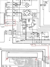
My reading of the Caution notice on p.4 of the Marantz TA 170 AV Service Manual seems to indicate that it is very similar to the TA110 but obviously some things have changed. In the parts list for some parts, it specifies what the part number was for a TA-110 and now for a TA-170. The display module has only the one part number listed, so based on this I was hoping that the display module would be the same one used in both models and therefore the backlighting would be powered the same way.

It is a FIP7P8C (Marantz part # HQ30705060) which uses a fluorescent tube for backlighting. The link is all I could find in the way of spare parts by searching for the part type and also the Marantz spare part number. You may have better luck.

The fluorescent tube (presumably not separately removable from the module?) is powered by a 2.1V AC supply directly from a secondary winding of one of the power transformers.

Perhaps check if there is this voltage being supplied to the display module on pins 1 & 26 or on the appropriate transformer connections.

Here's a composite image from the schematic which may help.

Block Image

(click on image to enlarge)

If the transformer winding is faulty, I couldn't find a replacement transformer either.

War diese Antwort hilfreich?

Bewertung 3

17 Kommentare:

Yes the 170 looks exactly like mine but different color. So you think the tube is not replaceable? I'm not sure its fluorescent because it's was not as bright as what I've seen from that type of lighting. How do I add pictures in comments here. Also can you look at another question I posted for this model? How to unplug PCB connectors on amp/receiver I'm trying to unplug connectors to get access to the display through the front panel and 2 flat wires are too short.

Also I've identified the secondary transformer poles on the P700 (P704 on your schematic) to the PR00 (PR04). I have two sets of 3 poles J802-3-1 then J805-4-6 and one set of 2 under them J808-7. Would these 2 seperate ones be the 2.1v J817-18 from your schematic? Which voltmeter leads should go on pole and on pin ? Never done this before same for reading schematics. Newbie here. Lol

Thanks

von

@jazzier

If two of the transformer outputs have 3 terminals and the other one has only 2 terminals then it should be the 2.1V AC output.

If the fluorescent tube is faulty you should be able to measure 2.1V AC directly across the the 2 terminals. Doesn't really matter which way as it is AC not DC.

Be safety aware as the power needs to be switched on in the receiver.

As for unlpugging the connectors I'm not sure. There seems to be a plastic base receptacle fitted to the board and the plug seems to be pushed down on it. I would use a screwdriver and try to gently lever the plug upwards between where the plug joins the base. I think you can see where it meets. . Alternatively use bull nose pliers (or similar) and grip the plug and gently rock back and forwards, or side to side while trying to lift the plug and see if it comes off that way i.e. try to wiggle it off. Use a finger etc to place downward pressure on the board next to the connector so that when trying to lift you're not lifting the board as well if the plug doesn't want to come.

As for brightness, fluro tubes lose brightness over time as they age the same as overhead fluros that are used in ceiling lights.

You can add images to your QUESTION (can't be done in comments). here's how Bilder zu einer vorhandenen Frage hinzufügen.

von

What about Pin 1 and 26 to pole terminals. Both wires are blue. Which goes to which since I don't have a diagram of mine?

As for the connectors I was able to lift the ears on the sides but the part that is attached to the wire sleeve (which has 1 closed side, 2 ears and a thin part attached on the sleeve on the open side) just tilts upwards but the wires are still in the base and I can't pull much on the actual wire because that small one (7mm by 5mm) is kind of wiggly at it's base and hard to hold down on the board so it doesn't brake the soldering. Good thing I am patient. I know lots of people who would have abandoned at this point. Lol

And thank you for all the info. Greatly appreciated.

von

@jazzier

With the two blue wires it doesn't really matter as it is AC power i.e. not polarity dependent. Although you could use an Ohmmeter and check whether pin 1 goes to term.5 and pin 26 goes to term. 4 on the connector if you want to. Do this with the power off of course. ;-)

With the plugs you could try using a flat blade screwdriver and gently levering outwards from the top where the cable comes into the connector i.e. slide driver down into connector next to cable where it goes into connector and see if that works by opening the connector up. Hopefully it isn't a one time plug, not meant to be unplugged.

von

So I just try with power on pin 1 and then pin 26 to any blue wire and if I get nothing with both wires then there's a problem with the transformer to the terminals or with the circuit to the display (on PR00) or with the display's circuit pins VR01 in your manual? If I get nothing should I test for continuity (with power off) from the transformer to the poles' blue wires? Is that a thing in this context?

Thanks

von

12 weitere Kommentare anzeigen

Einen Kommentar hinzufügen

Antwort hinzufügen

Jazzy wird auf ewig dankbar sein.
Seitenaufrufe:

Letzte 24 Stunden: 0

Letzte 7 Tage: 5

Letzte 30 Tage: 32

Insgesamt: 813