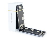
Einleitung
Use this guide to fix a faulty logic board in your iPhone 6s. Repairing a logic board may require micro-soldering.
A faulty logic board can also be replaced using the steps in this guide. It's important to note that each iPhone's logic board and Touch ID fingerprint sensor are paired at the factory, so replacing the logic board will disable Touch ID unless you also install a replacement home button that has been properly paired to your new logic board.
You can also use this guide for reference to replace the logic board EMI shield stickers.
See this iPhone 6s iTunes Hardware Restoration guide to help fix your phone’s logic board.
Was du brauchst
Einführungsvideo
Fix iPhone 6s iTunes Error
-
-
Remove the two 3.4 mm P2 Pentalobe screws on the bottom edge of the iPhone, on either side of the Lightning connector.
-
-
In diesem Schritt verwendetes Werkzeug:Clampy - Anti-Clamp$24.95
-
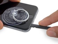
If you don't have an Anti-Clamp, follow the next three steps to use a suction handle.
-
Apply mild heat to the lower edge of the iPhone using an iOpener or hair dryer for about a minute.
-
-
-
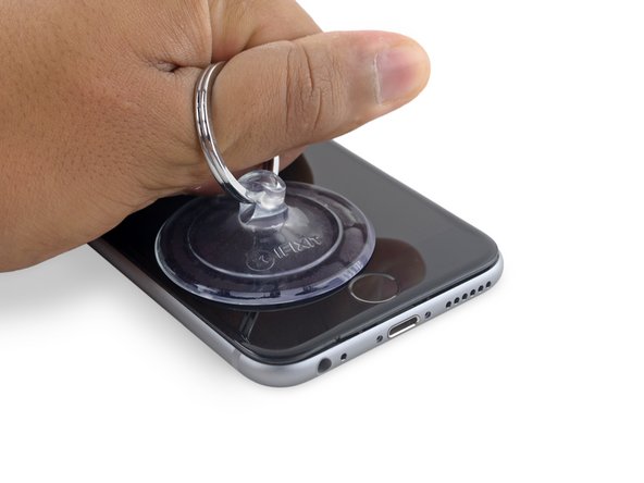
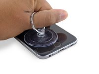
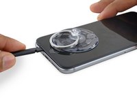
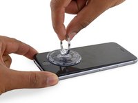
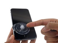
Apply a suction cup to the lower left corner of the display assembly.
-
Take care not to place the suction cup over the home button.
-
-
-
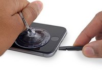
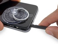
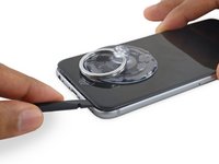
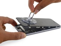
Pull up on the suction cup with firm, constant pressure to create a slight gap between the front panel and rear case.
-
-
-
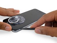
Place the flat edge of a spudger into the gap between the screen and rear case, directly above the headphone jack.
-
-
-
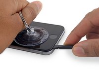
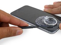
Twist the spudger to widen the gap between the front panel assembly and the rest of the phone.
-
-
-
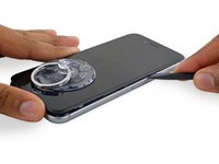
Insert the flat end of the spudger on the left side of the phone, between the display assembly and rear case.
-
Slide the spudger up the side of the phone to separate the adhesive and pop the clips free.
-
-
-
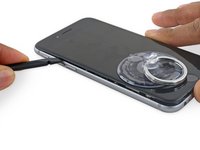
Remove the spudger and reinsert it on the bottom edge, where you pried the phone open.
-
Slide the spudger to the right, along the bottom edge of the phone.
-
-
-
Slide the spudger up the right side to continue separating the adhesive and popping the display clips free from the iPhone.
-
-
-
Pull up on the nub on the top side of the suction cup to remove it from the front panel.
-
-
-
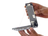
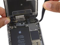
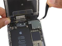
Gently grasp the display assembly and lift it up to open the phone, using the clips at the top of the front panel as a hinge.
-
Open the display to about a 90º angle, and lean it against something to keep it propped up while you're working on the phone.
-
Add a rubber band to keep the display securely in place while you work. This prevents undue strain on the display cables.
-
-
In diesem Schritt verwendetes Werkzeug:Magnetic Project Mat$19.95
-
Remove two Phillips screws securing the battery connector bracket, of the following lengths:
-
One 2.9 mm screw
-
One 2.2 mm screw
-
-
-
Use the point of a spudger to disconnect the battery connector by prying it straight up from the logic board.
-
-
-
Push the battery connector away from the logic board until it stays separated from its socket, so as to avoid any accidental connection to the battery while you work.
-
-
-
-
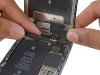
Remove the following four Phillips screws securing the display cable bracket:
-
Three 1.2 mm screws
-
One 2.8 mm screw
-
-
-
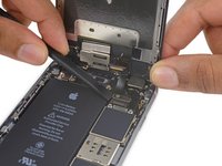
Use a spudger or a clean fingernail to disconnect the front camera flex cable by prying it straight up from its socket on the logic board.
-
-
-
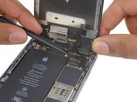
Disconnect the digitizer cable by prying it straight up from its socket on the logic board.
-
-
-
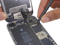
Disconnect the display cable by prying it straight up from its socket on the logic board.
-
-
-
Use the flat end of a spudger to disconnect the rear camera from its socket on the logic board.
-
-
-
Remove the following two Phillips screws over the rear camera bracket:
-
One 1.6 mm screw
-
One 2.0 mm screw
-
-
-
Insert a spudger to the side of the camera, between the rear case and the camera module.
-
Gently pry up on the camera to nudge it out from its housing.
-
-
-
Insert a SIM card eject tool or a paperclip into the small hole in the SIM card tray.
-
Press to eject the tray.
-
-
-
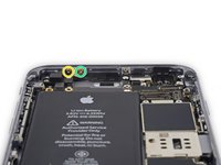
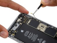
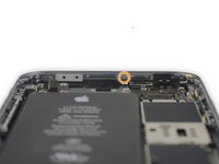
Remove the two 2.3 mm Phillips screws securing the upper component cable connector bracket.
-
-
-
Remove the following five Phillips screws securing the top left Wi-Fi antenna:
-
Two 1.5mm screws
-
One 2.3 mm screw
-
One 1.9 mm screw
-
One 2.0 mm screw
-
-
-
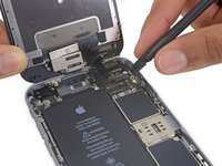
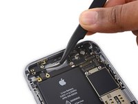
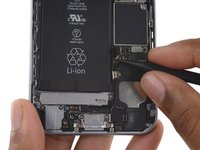
Use the flat end of a spudger to disconnect the audio control cable from its socket on the logic board.
-
-
-
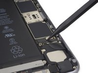
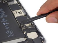
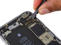
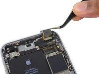
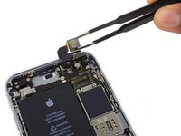
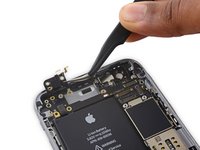
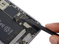
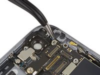
Use the pointed tip of a spudger to disconnect the antenna cable from its socket on the upper right corner of the logic board.
-
-
-
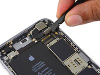
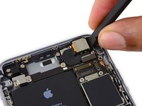
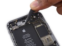
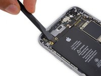
Use the pointed tip of a spudger to disconnect the antenna cable from its socket on the lower left corner of the logic board.
-
-
-
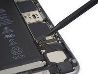
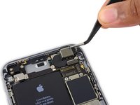
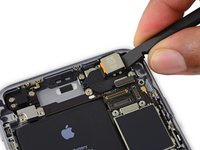
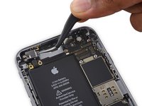
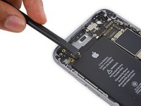
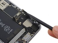
Insert the flat end of a spudger underneath the Lightning connector ribbon cable. Lift up to disconnect it from its socket on the logic board.
-
-
-
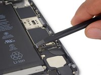
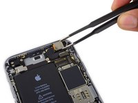
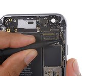
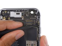
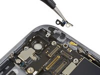
Gently pull up on the antenna cable to de-route it from the two clips on the right side of the logic board.
-
-
-
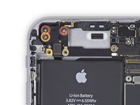
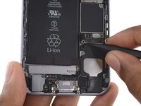
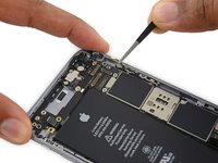
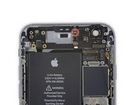
Remove the following two Phillips screws:
-
One 2.5 mm screw at the top of the logic board
-
One 1.4 mm screw set into the upper edge of the rear case
-
-
-
Remove the final three screws securing the logic board to the rear case:
-
One 1.9 mm Phillips screw
-
One 2.5 mm hex nut
-
One 1.8 mm Phillips screw
-
-
-
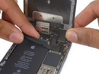
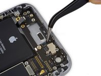
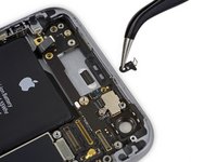
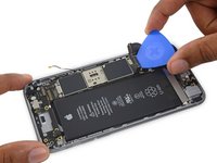
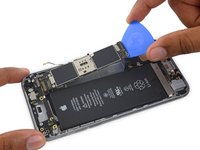
Insert an opening pick below the lower edge of the logic board, between the board and the loudspeaker.
-
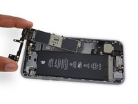
Use the opening pick to gently lift the logic board out of its housing.
-
Remove the logic board.
-
-
-
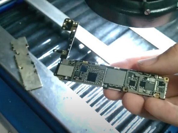
Remove the protective cover from the logic board.
-
Remove the black sticker from the logic board.
-
-
-
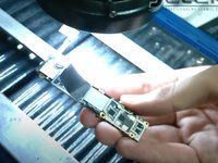
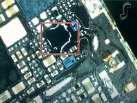
Place a heat shield over the other parts of the motherboard to avoid overheating.
-
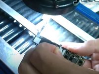
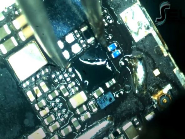
Heat the affected area with a heat gun to reflow the solder.
-
-
-
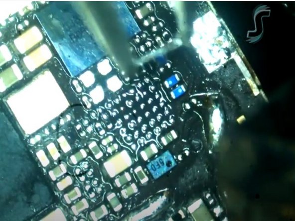
Re-solder a new tristar chip onto the logic board.
-
Apply a small amount of isopropyl alcohol to the areas where flux was applied.
-


To reassemble your device, follow these instructions in reverse order.
To reassemble your device, follow these instructions in reverse order.
Rückgängig: Ich habe diese Anleitung nicht absolviert.
10 weitere Personen haben diese Anleitung absolviert.