Einleitung
This is a prerequisite-only guide! This guide is part of another procedure and is not meant to be used alone.
Use this guide to remove the mainboard assembly in your GuliKit KingKong 2 Pro.
Was du brauchst
-
-
Use a Phillips #00 screwdriver to remove the four 11 mm-long screws securing the back cover.
 Frag FixBot
-
-
-
Insert an opening pick into the gap between the front assembly and the back cover at the bottom edge of the controller.
-
Tilt your opening pick downwards to widen the gap.
-
-
-
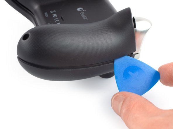
Insert an opening pick into the gap between the front assembly and the back cover at the outside of the right controller handle.
-
Slide the opening pick along the gap to separate the front assembly from the back cover.
-
-
-
Insert an opening pick into the gap between the front assembly and the back cover at the outside of the left controller handle.
-
Slide the opening pick along the gap to separate the front assembly from the back cover.
-
-
-
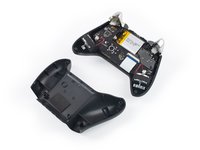
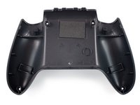
Separate the back cover from the front assembly and remove it.
-
-
-
In diesem Schritt verwendetes Werkzeug:Tweezers$4.99
-
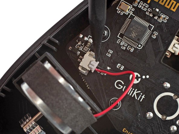
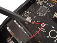
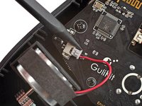
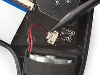
Use the point of a spudger to disconnect the right vibration motor by pushing the connector straight out of its socket.
-
-
-
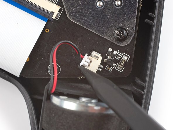
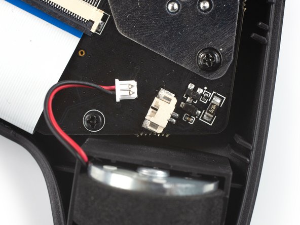
Use the point of a spudger to disconnect the left vibration motor by pushing the connector straight out of its socket.
-
-
-
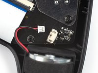
Remove the vibration motors by lifting them out of the controller housing.
-
-
-
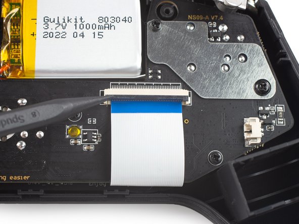
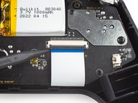
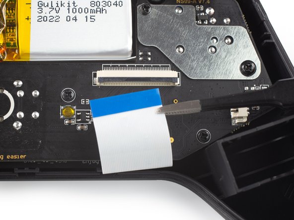
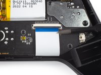
Use a spudger, an opening tool, or your fingernail to flip up the small, hinged locking flap on the interconnect cable's ZIF connector.
-
-
-
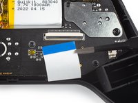
Use a pair of blunt nose tweezers to disconnect the interconnect cable by pulling the cable straight out of the connector.
-
-
-
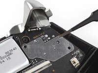
Use a Phillips #00 screwdriver to remove the screws securing the mainboard assembly:
-
Four 7.8 mm-long screws.
-
Two 11 mm-long screws.
-
-
-
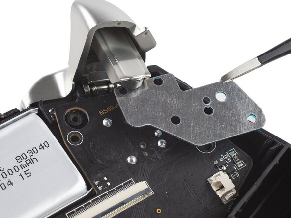
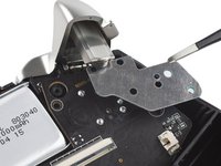
Use a pair of blunt nose tweezers to remove the metal shield from the mainboard assembly.
-
-
-
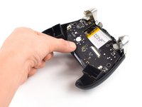
Remove the mainboard assembly by lifting it out of the controller housing.
-


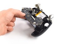

To reassemble your device, follow these instructions in reverse order.

