
Dell Inspiron B130 Motherboard Replacement
Einleitung
Zu Schritt 1 der AnleitungReplacing a motherboard is a complex repair that is rarely necessary. If your Dell Inspiron B130 is experiencing issues such as failing to power on, freezing, or unexpected shutdowns, these problems are often caused by other hardware components like the RAM, hard drive, or power supply. Before proceeding with this guide, confirm that the motherboard is the actual cause of failure and not another replaceable component.
This guide will walk you through the step-by-step process of safely removing and replacing the motherboard in your Dell Inspiron B130. you will need a Phillips #0 screwdriver, tweezers, and an opening tool. The estimated time for this repair is 45 minutes, and the difficulty level is moderate. Follow the steps carefully to ensure a smooth installation and avoid potential damage to other components.
Was du brauchst


-
-
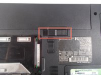
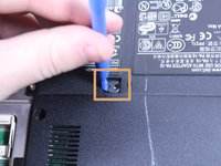
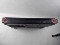
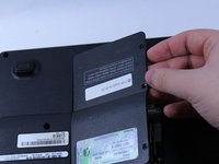
Remove the battery by flipping the two switches under the battery and pulling it out
-
-
-
Push the tab from the battery, downwards to unlock the battery.
-
The tab should be in the position next to the unlocked indicator.
-
-
-
Now, push the other tab (the one right under the battery) from right to left.
-
Now the battery will be loose; lift the battery up and out of the computer.
-
-
-
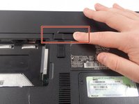
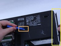
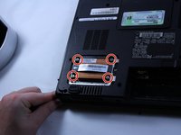
Remove the 8mm screw
-
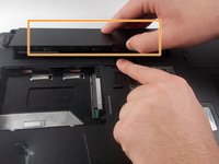
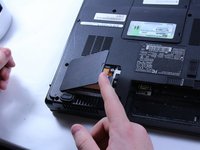
Use the plastic opening tool to push out the disk drive.
-
Pull the disk drive out with the opposite hand.
-
-
-
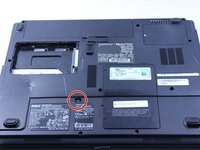
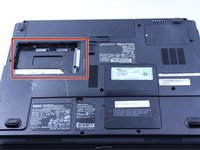
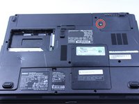
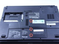
This particular computer is missing its hard drive.
-
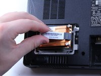
Remove the two screws.
-
Remove the plastic cover by lifting from the groove as indicated.
-
Remove the hard drive from the computer by lifting up and out.
-
-
-
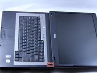
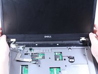
Put down the computer and open up the screen.
-
There is a long piece of plastic underneath the screen that you will have to remove.
-
-
-
Insert the plastic opening tool into the little slot.
-
Lift up gently and remove the plastic cover.
-
-
-
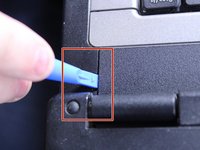
Lift keyboard up slightly and you will see the keyboard connection.
-
This black tab has to be lifted up to remove the keyboard.
-
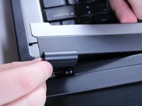
Put your finger underneath the tab and pull back gently as indicated.
-
You can now remove the keyboard.
-
-
-
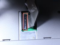
After opening the panel, you will see two cable connections attached to the screen.
-
Identify the one with blue tape this is the display connector that needs to be removed.
-
-
-
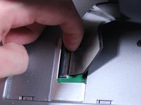
Locate the second connector next to the one removed in the previous step, This connector does not have blue tape but still needs to be detached. To remove it safely hold both sides of the connector firmly. Pull it straight apart avoid twisting or pulling at an angle to prevent damage.
-
-
-
Locate the two 6mm screws positioned directly beneath the screen. Use a Phillips #1 screwdriver to remove both screws. Keep the screws in a safe place, as they will be needed for reassembly.
-
-
-
Close the computer and flip it over so that the back is facing up.
-
Remove the two 6mm screws that are behind each of the screens pivot points. Use a Phillips #1 screwdriver to remove these screws.
-
Open up the screen and now it can be lifted up and off of the computer.
-
-
-
Use a flat head screwdriver to turn the screw one quarter turn into the unlock position.
-
Remove the CPU.
-
-
-
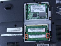
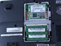
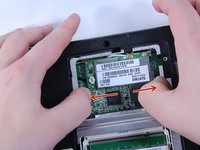
Remove the three 6mm screws.
-
Lift the plastic cover off to reveal the RAM and the Wireless.
-
-
-
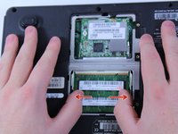
To remove the RAM, push outward against the metal brackets.
-
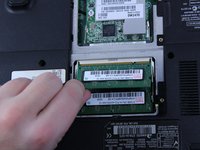
The first RAM will pop up so you can just pull it right out.
-
Repeat the first step again to remove the second RAM chip.
-
Installation is the reverse of removal.
-
-
-
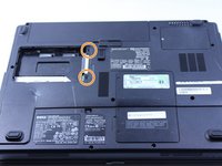
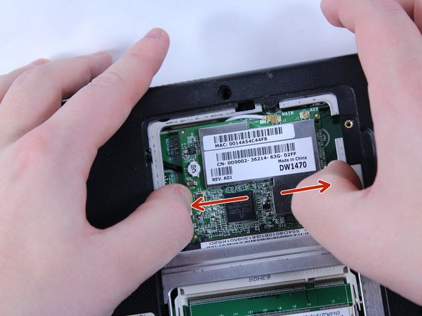
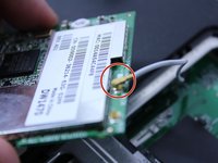
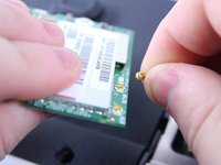
To remove the wire, hold the wireless chip firmly and pull the connection straight up off of the chip.
-
-
-
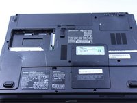
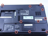
Use a Phillips #0 screwdriver to remove the twelve 8mm screws from the bottom of the laptop. Keep the screws organized to avoid losing them.
-
-
-
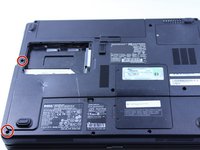
Turn the laptop over so that the keyboard side is facing up, then locate and remove the two 4mm screws positioned just below where the screen would be using a Phillips #0 screwdriver.
-
Remove the five remaining 6mm screws. Be sure to keep track of these screws, as they will be needed for reassembly.
-
-
In diesem Schritt verwendetes Werkzeug:Tweezers$4.99
-
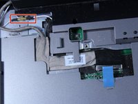
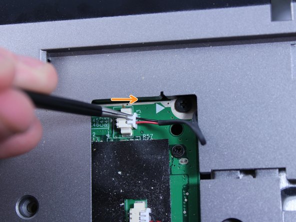
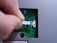
Disconnect the two connections carefully.
-
Do not pull by the wires! This can damage the connection. Use tweezers to grab by the white plastic piece and push outward.
-
-
-
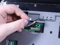
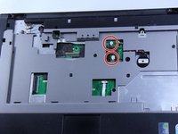
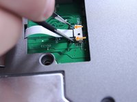
Disconnect this connection before proceeding.
-
Use tweezers to grab the small black connector and pull it straight back carefully. Avoid pulling on the wire directly, as this may cause damage to the connection.
-
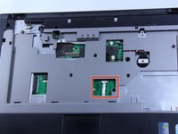
You can now disconnect this wire.
-
-
-
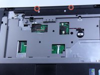
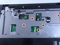
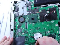
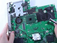
Lift and remove the entire cover/frame from the top of the motherboard. Gently pull up to detach it without using excessive force
-
Remove the motherboard by pulling it upward and sliding it to the right. Be careful not to damage any remaining connectors or components. If the motherboard feels stuck, double-check that all screws and cables have been disconnected.
-


To reassemble your device, follow these instructions in reverse order.
To reassemble your device, follow these instructions in reverse order.
Team

UMass Dartmouth, Team 1-8, Catania Fall 2016 Mitglied von UMass Dartmouth, Team 1-8, Catania Fall 2016
UMASSD-CATANIA-F16S1G8
3 Mitglieder
9 Anleitungen geschrieben