Einleitung
iSight acting more like iBlind? Maybe it's time for a new camera. Use this guide to replace a faulty camera.
Was du brauchst
-
-
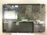
Remove the following ten screws securing the lower case to the upper case:
-
Three 13.5 mm Phillips screws.
-
Seven 3 mm Phillips screws.
-
-
-
Wedge your fingers between the lower case and the vent, and lift upward to release the two clips holding the lower case to the upper case.
-
Remove the lower case.
-
-
-
If present, grab the plastic tab attached to the battery connector and pull it toward the front edge of the device. For Late-2011 models the battery connector will not have a tab and is simply a plug that inserts straight down into the motherboard--to remove pry the plug straight up.
This step is a little difficult in reverse, that is, when re-attaching the battery. It helps to tilt the laptop up so you can see the edge of the board that accepts the plug. It may look like there are two slots for it, it goes in the bigger slot that is further away from the board.
Is this step really necessary? It is not part of the instructions how to replace the HDD in Apple's User Manual of the 2011 17" MBP.
As it says in the step: "Whenever working near the logic board, it is always wise to first disconnect the battery to avoid short circuits." It is not required, but it is simple insurance to avoid a $1000+ repair should you accidentally short components on the board with something metal.
There was no tab on my model. Battery is affixed to board and screws must be removed.
Mine also, and looks as if removing connector could damage motherboard.
Stephen -
The battery on my 17” mid-2010 (MC024LL/A -A1297 ) is held by 3 specialty screws CR-V1 (3-wings similar to Mercedes-Benz tri-star)
It has a tab which I pulled straight up
The connector to the motherboard came away easily by pulling toward the front edge.
* There is no tab on the A1297 (late 2011) model's battery connector. Be careful with the connector, it chips off the edges easily! Otherwise the same as bhodges2 & Stephen's notes.
** (Pleas also include the exact Model and Part numbers like P/N: MD311D/A; Mod.: A1297 in the comments and notes for your MBP)
Why are there no guides for the Late 2011 17" MacBook Pro A1297 (2.4GHz i7 quad core, MD311LL/A)??? I just replaced the RAM in mine and discovered that not only is there no tab on the battery connector, but the connector pulls straight up, perpendicular to the logic board, rather than parallel. I almost ripped the wires out of the connector by trying to pull it out parallel to the logic board like this guide instructed! After finally getting it out, my advice to those with the Late 2011 model is to use a spudger to loosen the edges of the connector then lift the connector straight up to get it out safely.
I replaced the display on my late 2011 model and noticed that it was quite different than the tutorial given here so I detailed all the differences to help others with late-2011 models on my blog: http://johnfixesstuff.blogspot.com/2014/...
jmueller -
With some dexterity and carefulness, the MagSafe could be removed from its place without the need to remove the whole logic board!
Same here, I used a head-band light to see it and got it done without removing anything but the battery connection, the charging port and the display data cable. Then I had to do it again because amazone sent me the wrong charging port, the board has different width between screw holes, and on closer look, different components soldered on, also. AND, one is labeled 2008, the other 2009… make sure you get the correct one, the other ( “wrong”? ) might work, but I’m not risking it! So why does the 2008 fit in my 17” macbook pro(5,2) mid-2009 and the one labeled 2009 does not fit ? It is what it is…
kr8luv -
The battery on my 17” mid-2010 (MC024LL/A -A1297 ) is held by 3 specialty screws CR-V1 (3-wings similar to Mercedes-Benz tri-star)
It has a tab which I pulled straight up
The connector to the motherboard came away easily by pulling toward the front edge.
-
-
-
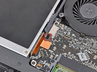
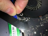
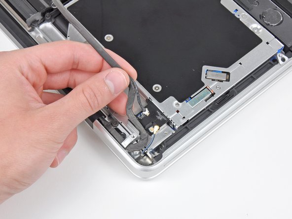
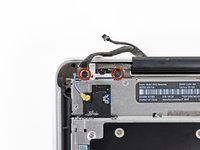
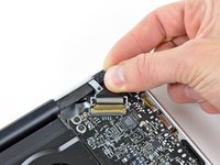
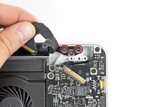
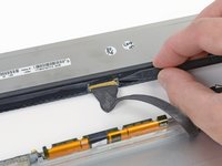
Use the tip of a spudger to push the small plastic cable retainer away from the camera cable socket for enough clearance to remove the camera cable.
I think I should have a photo of the plastic retainer as there may be more people like me who were afraid to take the part.
-
-
-
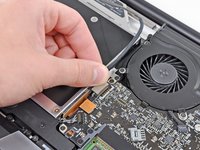
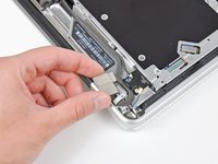
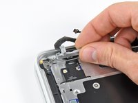
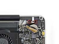
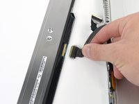
Pull the camera cable toward the optical drive opening to disconnect it from the logic board.
-
-
-
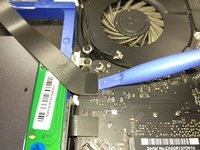
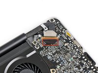
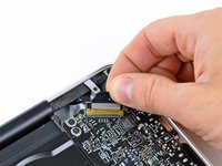
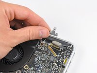
Carefully pull the Bluetooth cable toward the fans to disconnect it from the Bluetooth board.
-
-
-
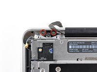
Use the flat end of a spudger to peel the thin plastic cover off the top and sides of the Bluetooth board housing. For late-2011 models check out the other picture because the connector location is in a totally different location.
-
-
-
Use the flat end of a spudger to pry the Bluetooth antenna connector up and off its socket on the Bluetooth board.
-
-
-
De-route the camera cable from the slot molded into the Bluetooth board housing.
-
-
-
Remove the two 7.1 mm Phillips screws securing the camera cable retainer to the upper case.
-
Remove the camera cable retainer from the upper case.
-
-
-
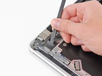
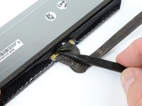
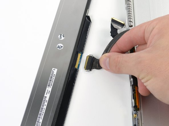
Lift the black plastic flap attached to the display data cable retainer and rotate it toward the DC-In side of the MacBook.
-
Pull the display data cable out of its socket.
-
-
-
Remove the two 7.1 mm Phillips screws securing the display data cable retainer to the upper case.
-
Remove the display data cable retainer.
-
-
-
Remove the two outer 6.8 mm T6 Torx screws from each of the two display brackets (four screws total).
I viewed a YouTube video showing this process. There was a warning about the stripping of the Torx screws being common on this mid-2009 model MBP. Is that something you have come ever across? It's the only thing holding me back from attempting this myself. TY in advance!
Taking those hinge screws out can be difficult (they are fat, and they resist turning). In my first attempt I destroyed the Torx screwdriver bit (soft metal, I discovered, so the bit twisted into a corkscrew before it snapped off). After buying the ifixit screwdriver set I found that the driver bits were tough enough, but the screws still would not budge! So, I used a small mole-grip wrench to hold the metal part of the screwdriver, and GENTLY turned until I felt the screw give way with a click. Luckily, the threads did not strip. However, if you find that even with that extra torque from the wrench, it is still resisting in a big way, go one more step and try a very tiny drop of thread-loosening fluid on it. (That last suggestion, however, is risky, so be careful.... do not let any fluid get anywhere except the screw, and then give it time to work).
RichardL -
What's the url to the youtube video you mentioned?
Too late. I should have read the comments first but I was rushing. I just stripped two of them. They are in there super tight.
I just did this now (11:21 am, Sept 18 2014) A tip for removing glass bezel on the frame if you don't have a heat gun. I used a very sharp but super thin razor (the one for shaving) and slice the adhesive. Be careful not to hit the lcd. After slicing all around, get any thin plastic card and slide it all around the bezel until the glass comes off. I have a mid 09 macbook pro 17" that had a broken lcd and a 2010 macbook pro i7 17" that had a logic board problem but good lcd. Both A1297. I did it twice using my method.
-
-
-
-
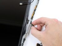
While holding the display and upper case together with your left hand, remove the remaining T6 Torx screw from the lower display bracket.
-
-
-
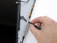
Remove the last remaining T6 Torx screw securing the display to the upper case.
-
-
-
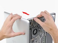
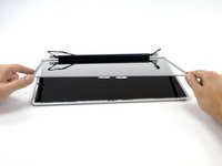
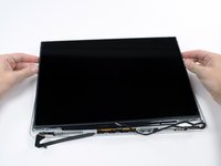
Grab the upper case with your right hand and rotate it slightly toward the top of the display so the upper display bracket clears the edge of the upper case.
-
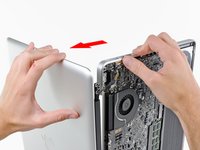
Rotate the display slightly away from the upper case.
-
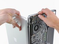
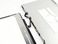
Lift the display up and away from the upper case, minding any brackets or cables that may get caught.
-
-
-
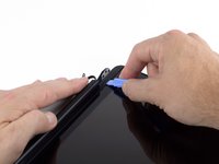
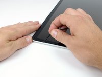
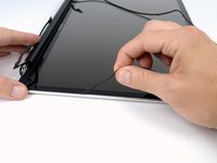
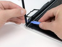
Insert a plastic opening tool underneath the black rubber gasket at the bottom left corner of the display assembly.
-
Gently pry the wide edge of the gasket up from the back case.
-
-
-
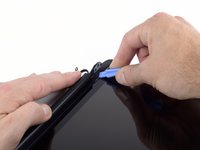
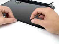
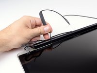
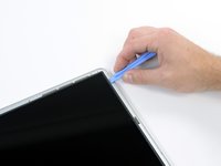
Starting with the freed corner, pull the left gasket off the left side of the display assembly.
-
-
-
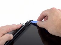
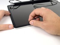
Continue pulling the display gasket off the display assembly across the top edge.
-
-
-
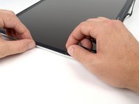
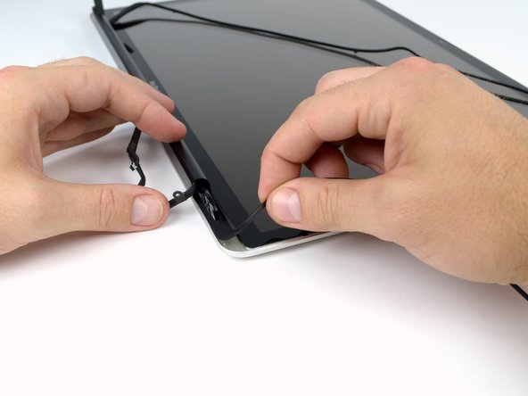
Continue pulling the display gasket off the display assembly down the right side.
-
Pull the gasket off the bottom edge of the display to completely free it and set it aside.
-
-
-
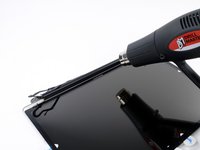
Before starting, be sure to clean the display glass with a lint-free cloth moistened with a mild solution; it will make the suction cup adhere better, and will make checking for dust on reassembly easier.
-
With the heat gun set to low, start by heating the outer black border near the upper right corner of the glass panel.
I didn’t want to wake people in the house at midnight with a heat gun so i tried something else and it worked fantastically well.
1) i used an oil-filled electric radiator and set it to high
2) I put a small box (about 6 x 9”) on that radiator
3) i put the display face-down on the box ; the box deflects the heat to the edges and slowly heats the edges to a nice hot temp not too hot.
4) I used 4 credit cards as i didn’t have guitar picks. I was able to do all four sides with one heating process.
I was still able to touch the surface it was probably under 180° (the magic temp that virtually any electronic device can survive).
I’ve used toaster ovens to preheat an iPad for screen removal; this works much better it only heated the edge.
-
-
In diesem Schritt verwendetes Werkzeug:Heavy-Duty Suction Cups (Pair)$14.95
-
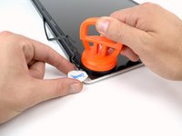
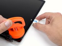
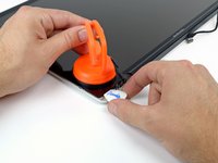
With the panel sufficiently heated, fasten a heavy-duty suction cup near the lower right corner of the display glass.
-
To attach the suction cups we sell, first position the suction cup with the movable handle parallel to the face of the glass panel. While lightly holding the suction cup against the glass, raise the movable handle until it is parallel with the other handle.
-
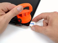
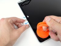
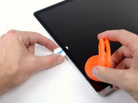
Gently lift the corner of the display glass enough to insert a guitar pick between it and the display assembly.
-
Use the guitar pick to gently pry up the adhesive securing the front glass to the display.
-
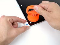
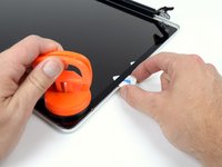
Pry up the glass panel along the right edge of the display up to the halfway point.
-
Leave the guitar pick in place halfway up the right side of the display and remove the suction cup.
-
-
-
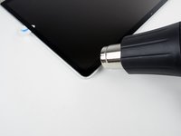
Use a heat gun to soften the adhesive under the display glass along the right and top edges of the display.
-
Attach a suction cup to the upper right corner of the front glass panel.
-
Pull up on the glass panel while you use a second guitar pick to separate it from the rest of the display assembly.
-
Continue working along the right edge of the front display glass until it is separated from the display.
-
-
-
Work along the top edge of the display assembly, carefully prying the adhesive up with the guitar pick.
-
Stop prying about an inch before you reach the iSight camera. Leave the guitar pick in place and remove the suction cup.
-
-
-
Repeat steps 22 through 24 for the left side and the left top edge of the display.
-
-
-
After prying up the three edges of the display glass, you should have four guitar picks resting underneath the panel, as shown.
-
-
-
With the heat gun set to low, heat the bottom edge of the display to soften the adhesive holding the glass in place.
-
Slowly lift the top edge of the glass panel and gently rotate it out of the display.
-
-
-
Holding the clutch cover firmly, slide it towards the right display hinge.
-
-
-
Lifting the left edge of the clutch cover, gently rock it back and forth on its long axis while pulling it away from the display.
-
Remove the clutch cover from the display, minding any cables that may get caught.
How the he'll do I get it back on?
How the he'll do you get the cover back on?
-
-
-
Remove the four 2.3 mm Phillips #00 screws securing the LCD to the rear display bezel.
-
-
-
Lift one of the top corners of the LCD panel out of the rear bezel with a plastic opening tool.
-
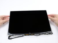
Grasp the top corners of the LCD and rotate it upwards, slightly out of the display.
-
Pull the LCD toward the top of the display panel, freeing the screw tabs from underneath the rear display bezel.
-
-
-
Flip the LCD over and lay it face down, being careful to not put too much stress on the display cable.
-
Peel the piece of tape covering the display data cable connector away from the edge closest to the LCD.
-
-
-
Use the tip of a spudger to flip up the thin steel retaining clip securing the display data cable to its socket on the LCD.
-
Pull the display data cable straight away from its socket on the LCD.
-
Lift the LCD out of the display assembly and set it aside.
-
-
-
Remove the two 2.7 mm Phillips #00 screws securing the camera board to the rear display bezel.
-
-
-
Use the flat end of a spudger to pry the camera board cable from its socket on the underside of the camera board.
-


To reassemble your device, follow these instructions in reverse order.
To reassemble your device, follow these instructions in reverse order.
Rückgängig: Ich habe diese Anleitung nicht absolviert.
5 weitere Personen haben diese Anleitung absolviert.


Ein Kommentar
If you’re replacing the board and the camera, make sure the part numbers match. There are different cameras out there that will attach to different boards but they will not work. To know if you mismatched one, your Mac will come on and the fans will run a full speed and the OS will be extremely slow. Also, the camera will not work. There are different ones you can use on different machines but I highly recommend replacing both the camera and the board to avoid the situation all together.
important to reassemble the "lower case" successfully: the threads of the seven 3mm phillips screws are drilled at an angle :-/
mysterioes - Antwort
Same issue with me. After reassembling my 13-inch and my 17-inch, one of the screws are sticking out ever so slightly. Very annoying, especially since I scratch whatever surface I'm on now.
Kyle Spadaro -
Very important note; this guide is NOT correct for the Macbook Pro 17" A1297 late '11.
The A1297 has an assembly adjacent to the optical drive, identifiable by 4 antenna connectors, 1 usb cable (with very small connector) and one PCI-e flat cable running across the optical drive.
I did not take pictures, but found one on the web. I'm very new to iFixit and have no idea yet on how to create a guide, but here's the picture showing the assembly on top (this pic only has 3 antenna wires, the A1297 has 4, but at least you'll know what to look for.
- carefully undo all connections and 2 screws
- remove the assembly and flip it over
- again carefully remove the shielding tape
- undo 3 tiny screws
- gently pry the airport card from the assembly (the flat cable will be a bit of a pain)
- reverse process with replacement card.
image can be found here:
https://dl.dropboxusercontent.com/u/2446...
Remon - Antwort
It helps if you mark the holes where the long screws go so you can easily find them when the time comes to button things up. Also, a little dish or custard cup to hold those tiny screws is essential.
Human - Antwort
3 x 13.5 mm screws are actually TWO different types! Return to EXACT SAME HOLES.
-I discovered this on my mid-2010, but from comments, sounds like it may affect other models as well
2 x 13.5 mm screws are pointed ends
1 x 13.5 mm screw is a FLAT end <- CORNER HOLE
These areTWO slightly different lengths, and must return to correct holes. If you put the flat end screw in the wrong hole, it will stick out slightly. If you put either of the pointed screws in the wrong hole, they will go in all the way, but will not catch threads, and will simply fall out when laptop is flipped back over.
scottbernardis - Antwort
I printed out the image above and taped each screw to the photo as I removed each one, just to make sure I put them in the right location.
Grace Morris - Antwort
This is a brilliant suggestion! I did this for all the steps that involved removing screws, numbered the sheets, and that made it very easy to put it all back together in reverse. Thanks!
Steve Adamczyk -
Be sure to use Loctite on the screws when re-attaching the bottom of the computer. The screws can and will fall out once they have been removed for repairs if you do not put Loctite on them when you reuse them. Otherwise, purchase new screws before repairing the computer as the new screws come with Loctite material on them. (I have personal experience with this problem.)
johnpartridge - Antwort
Be sure NOT to Buy this Battery from iFixit. I bought it from eustore.ifixit.com and the Condition of Battery is : Service Battery ,
from the &&^&^$^ first day.
Till today my battery Cycle Count is: 80.
I’ve tried everything as: Battery Calibration, resetting the SMC, PRAM, reinstalling the battery,
and Service Battery warning still there.
Just DO NOT BUY crappy, trash from here.
I have very bad experience.
Doruntin Koci - Antwort
Hi Doruntin,
we’re more than sorry to hear about your bad experience.
I’ll inform our customer service team who’ll reach out to you and offer either a replacement or reimbursement.
If ever you’d need assistance again, please feel free to directly write to eustore@ifixit.com, as comments are not regularly checked for service issues.
I’m confident that we’ll find the solution that suits you best!
Sandra Hiller -
PLEASE OBSERVE: The image of the left speaker used is NOT for a 2011 model. A 17inch MacBook Pro A1297 - LEFT SPEAKER + MICROPHONE - 2011 has IDENTIFYING NUMBER: Apple Part #:922-9821, 922-9822. And its COMPATIBILITY: 17 inch MacBook Pro Unibody A1297 - Early 2011 MC725LL/A 2.2 i7 - Early 2011 MC725LL/A 2.3 i7 - Late 2011 MD311LL/A 2.4 i7 - Late 2011 MD311LL/A 2.5 i7
kenneth krabat - Antwort