Einleitung
Diese Anleitung zeigt dir, wie du einen defekten Lüfter in deiner Nintendo Switch Spielkonsole austauschen kannst.
In der Switch sind JIS-Schrauben verbaut, zur Not passen aber auch Bits für Kreuzschlitzschrauben. Sei aber sehr vorsichtig und beschädige die Schraubenköpfe nicht. Die Bits von iFixit können auch für JIS-Schrauben verwendet werden.
Hinweis: Wenn du das Abschirmblech ausgebaut hast, musst du die Wärmeleitpaste zwischen der Oberfläche und dem Kühlkörper ersetzen. Normale Wärmeleitpaste ist nicht geeignet, größere Spalten zu überbrücken, der beste Ersatz ist K5 Pro viskose Wärmeleitpaste.
Hinweis: Diese Anleitung und das von uns verkaufte Ersatzteil ist für das originale Nintendo Switch Modell von 2017 geeignet, aber auch für das neuere Modell von 2019 (Modellnummer HAC-001 und HAC-001(-01)).
Was du brauchst
-
-
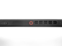
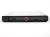
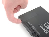
Drücke und halte den kleinen runden Knopf auf der Rückseite des Joy Con Controllers.
-
Halte den Knopf weiterhin gedrückt und schiebe den Controller nach oben.
-
-
-
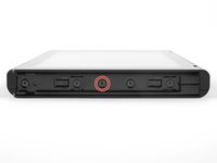
Schiebe den Joy Con nach oben ganz aus dem Gerät heraus.
-
-
In diesem Schritt verwendetes Werkzeug:Magnetic Project Mat$19.95
-
Entferne die vier 6,3 mm langen Tri-Point Y00 Schrauben von der Rückabdeckung.
I think my screws are stripped, any way to get them out?
I hear that using a rubber band can help? Not 100% sure on that though.
Pifase -
My top 2 screws are stripped, one into triangle, the other circle, rather than triangle spokes.
This happened when I replaced the micro-sd card slot, which turned out to have replaced the broken one with another one that turns out to be broken. I need to fix the fact that when I reapplied the back cover, the vent was misaligned.
I had huge problems removing the bottom two screws. I continued with the next steps and lifted the plastic shell as much as possible while using the screwdriver and it became an ease.
y0 works best. Press HARD at beginning then ease off to finish.
I haven't tried neither solutions that I am gonna propose here but
1. Poor some Isopropyl Alcohol, one small drop will do, get a piece of cotton (not any clothing) and dip it in the Isopropyl Alcohol, apply and then try to get a grip with tweezers and turn it out
OR (I do not reccomend it since it can cause huge damage if done wrong)
2. Grab a small drill and drill through the screw. Keep in mind; the screw is very small.
If you do one of these and it goes wrong, I am not responsible for that.
-
-
-
Nimm einen JIS 000 Schraubendreher oder ein Ph000 Bit von iFixit und entferne folgende Schrauben, mit denen die Rückabdeckung befestigt ist:
-
Eine einzelne 2,5 mm Schraube an der Oberkante des Gerätes.
-
Zwei 2,5 mm lange Schrauben an der Unterkante des Gerätes
Hey guys, I tried removing the upper screw and it won't go out(neither will it go in) any tips how to fix this?
Thanks
The screw boss might be stripped out. Has the device been taken apart before? If you can unscrew it a little bit to get the screw to peek out, maybe try and grab it with some pliers as a last-ditch effort.
I have the same problem. The JIS 000 tool works great on the joy con rails per step 5 but refuses to turn the bottom two 2.5 mm screws as in step 4. These bottom screws are noticeably smaller than the screws as in step 5. The JIS 000 does not get down into these screws. Hopefully they haven’t been stripped by the wrong tool. So is there a JIS tool that is smaller than 000? I’m stuck at this point…
We used the JIS 3.0mm screwdriver for both top and bottom screws and it worked
Fun fact: these screw into little plastic tabs that stick out of the rear panel. Apparently those tabs are fragile and easy to just break off…
If the screw is turning but not coming out, the plastic tab that it screws into is probably damaged or broken. You’ll need to try to pry the screw out with tweezers as you unscrew it. It is not the end of the world if you can’t screw these back in during reassembly.
this screws are way too fragile and way too small so be careful when taking them off dont use much force and unscrew also one of them fell somewhere and spent 30 mins searching for it
PH000 will work if you don’t have JIS000. The large IFIXIT kit has both and I lost JIS000. Just be very careful as you can strip the heads when removing or inserting easier.
One thing that worked pretty well for me with the screws not coming out is slightly prying on the back cover to put them under some tension
I just came here to also confirm and say thanks to Florian for the tip. This saved me a lot of time and frustration.
Quick note, these screws are not magnetic. A magnetic screwdriver will hold onto any of the others safely, but you need to be careful not to drop these ones in particular.
These would just keep rotating and not come out. What worked was, as Florian Kraupa suggested, i slid a plastic pick just between the 2 shells near the screws to prise it open slightly, then unscrewed and out they came. They're the smallest screws I've ever almost not seen before, so be careful with them.
Der Tausch von Akku (separate Anleitung) und Lüfter ging einfach vonstatten. Die Anleitung ist echt gut und leicht verständlich. Man sollte aber gewohnt sein, mit extrem kleinen Anschlüssen, Schrauben und Platinen zu arbeiten, da alles da drin recht klein ausgelegt ist und keine Toleranz für grobschlächtiges Arbeiten erlaubt! Meine Switch ist nun wieder wie neu :) - Danke iFixit!
The swapping of battery (separate instruction) and fan was fairly manageable. The instructions are easy to understand. One should be used to handle with extremely finnicky connectors, screws and circuits as the components are really small and do not allow any tolerance for rough handling at all! My Switch is good as new again :) - Thank you iFixit!
My original switch bought on launch day does not have any of these screws. I'm guessing they fell out since the plastic tabs they attach to are broken. FYI, in case anyone else does not have these screws...
-
-
-
In der Mitte auf jeder Seite des Gerätes befindet sich eine 3,8 mm JIS 000 Schraube. Nimm einen JIS 000 Schraubendreher/Bit oder ein Original PH000 Bit von iFixit und drehe sie beide heraus.
I tried my JIS 000 on Step 5 and was unable to get the screw to budge. It’s partner from the other side came right out with no trouble. Don’t really want to narf up the screw, so I bailed out. Anyone else have this issue?
Could just be torqued down a bit more! I’d recommend making sure the driver bit seats nicely into the screw, apply some downward pressure, and slowly twist to try and back it out. Good luck!
Yeah I’m having this exact issue. Screw stripped and now I’m stuck. Wish I hadn’t even started.
What worked for me here was a Phillips 000, not a JIS 000
My kit only has two screwdriver heads! The package was open when I received it!
I had this issue as well. Screw was irreparably stripped. If you can get every other screw out, just keep applying pressure with a flat head screw driver right above the stripped screw and try to break the plastic piece holding onto the screw. It's a very minor invisible bit of damage that will allow you to continue the repair.
after getting all the other screws off I just hinged the back part away and it snapped off neatly where the rusted screw is. not the best solution but it worked.
Steve T -
One of my screws was SUPER attached too, but after following a bit noticed the one other in the left that got out nicely, had the plastic tab broken already! So I went ahead and broke the other tab too. So the two side screws are now holding nothing. But I think it will work thanks to the other 4 or 5 screws. Too bad!
-
-
-
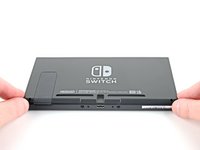
Klappe den Aufsteller auf der Rückseite des Gerätes mit den Fingern heraus.
-
-
-
Nimm einen JIS 000 Schraubendreher/Bit oder ein Original PH000 Bit von iFixit und entferne die 1,6 mm JIS 000 Schraube in der Vertiefung für den Aufsteller.
-
Klappe den Aufsteller zu.
-
-
-
Öffne die Cartridge-Klappe.
-
Hebe die Rückabdeckung von der Unterseite des Gerätes her hoch und entferne sie.
How to remove micro SD port?
Pull straight up, press back into place when closing back up.
This step is missing in this guide. Here are the steps from another guide:
Step 9) Nintendo Switch rechte Joy-Con Sensorschiene austauschen
Step 10) Nintendo Switch rechte Joy-Con Sensorschiene austauschen
When I lifted up the back cover, it kind of stuck near the headphone port (even with cartridge slot open). But it wasn't a screw or anything and I kind of carefully pulled and wiggled and the cover came off ok
+1, there is definitely an extra clip there on my day 1 switch
I wasn't so careful here and found out during reassembly that I accidentally broke off the clip with the screw hole on the top of the back cover (the clip fell off the device when I turned it over), so I can't put the top screw back in, but oh well at least the back cover is still affixed to the device otherwise
If you're having trouble getting the back cover to fit during reassembly, check to make sure you don't have an SD card inserted in the slot. It will get in the way.
If you're like me, you might have inserted the SD card to verify your SD reader was working again after doing step 9 reassembly. If so, remove it before proceeding.
-
-
-
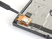
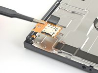
Nimm einen JIS 000 Schraubendreher/Bit oder ein Original PH000 Bit von iFixit und entferne die einzelne 3,1 mm JIS000-Schraube, mit der der microSD-Kartenleser befestigt ist.
-
-
-
In diesem Schritt verwendetes Werkzeug:Tweezers$4.99
-
Hebe den microSD-Kartenleser mit den Fingern oder einer Pinzette nach oben vom Gerät weg, löse ihn ab und entferne ihn.
Yes. The reverse is not so simple- you can’t see what you’re doing when you attempt to reconnect and it only takes one small error to completely bend the contacts on the connector. Very delicate.
if you very gently remove the foam pad sticker, you can at least see better how it lines up and can feel your way to a degree… then you can stick the pad back in. The pad seems pretty critical in keeping things in place once reassembled.
Definitely agree about not sticking the foam pad back on until the new SD card slot is connected. Saved a lot of headache. Great walkthrough and easy repair!
Tried several times to replace this SD reader module. As mentioned above, the issue is aligning the connectors together. It appears the foam tape is being used to hold the connection in place. (assuming you can make a viable connection) I am rather surprised at this design. In my experience, mylar ribbon cables like this usually slide into a small PC mounted socket. It appears Nintendo went the cheap route here. This design is prone to failure since it does not enable a positive connection - at least from what I can see.
I found it easier to connect it without the black foam pad so I could see and than add the foam pad over it. It was super easy and I an I 33 Mom doing this for my son. Was well worth the money for the kit saved us almost 100 bucks
Had my son follow this guide to fix his own switch where the ad card reader didn't work. And he did. Great instructions!!!! Thanks a million!
The only difficult part of following this guide is connecting the new sd card reader into the poorly designed motherboard connector. Its quite possible the sd card reader that came in the console wasnt broken at all.
The repair kit works just as advertised and even comes with stickers.
I’m still getting error 2002-2054 even after replacing memory card reader module. Thanks, Nintendo!
My switch won’t read my microSD card after I reassembled it (error 2016-0641) please help!
Tip: Keep the old SD reader piece loosely attached while you line up and gently press the new SD component into the connector on the motherboard. Once the new piece is snug, then carefully remove the old piece keeping the sticky foam in place.
I am a middle-aged mom with absolutely no special tech skills and I easily followed the directions and successfully fixed the broken SD drive. ifixit is the best!
Ah good! i have more confidence now in doing it once you said you're a middle age mom with no experience
I missed this bit about reconnecting the SD card reader under the foam pad and didn’t realise until my son pointed out a data storage problem?. All fixed in about 5 minutes taking advice from the replacing the SD card reader fix, especially removing the foam pad from the connector to better see and feel what you’re doing. All sorted!
Awesome guide! Very easy to do with the supplied kit
Tank you very much, and by tank I mean M1 Abrams, jokes apart easy and simple to follow
Thanks for the guide, I was struggling to find a solution, replaced more sd cards, before I stumbled upon this post. The Switch of my children works flawless again!
This helped me to reseat my SD card reader ribbon cable. I was getting the 2016-0641 error and no card work. A drop had dislodged the cable partially. And yes remove the foam pad gently to properly connect the cable. You can reuse the foam pad.
For anyone who ends up bending the pins like I did while trying to reseat the microSD card reader…
I suggest gently placing very thin tweezers (like the curved ones in the Pro Tool Kit) in the gap and very, very gently pressing them back into alignment. Took a little effort but I was able to realign them enough to sit it in place and have it later working after reassembling the console.
When reassembling, note the alignment pins in the left and bottom notches before tightening the screw
Super gemakkelijk te installeren met behulp van deze zeer duidelijke handleiding (met dank aan de vertalers!)
Wel even goed opletten op de aansluiting op het moederbord is zeer fragiel.
It is key to remember most out of the box issues with the SD card reader, do not require a replacement part and can be solved with disconnecting then re-connecting the reader at the motherboard.
Only when a simple re-seating at the connector doesn't work should you buy the replacement part.
I bought the kit and followed the directions. I plucked the black rubber foam off with a pair of eyelash tweezers. Putting the tiny screws back in place also was made easier using the tweezers. As for placing the SD card in place I think I got a bit lucky. I lined it up and gently pressed until it simply went into place. I do believe being gentle is the key there. But it went in and I put it back together. The deconstructing and reconstructing is what took the longest for me at least. I turned it on to verify it worked and then unpowered the unit and inserted the card. The system recognized and update right away and did it and then recognized the card! Just what I need for 20 something dollars. Son is happy and back to gaming.
Thank you for postingthis fix. The original sd card reader had come unplugged from the motherboard, so replacement reader will be a spare.
Anybody found a way to ensure the sd reader stays in place?
It was my first time repairing a Switch and the fan replacement wasn't too hard, but unfortunately I think there should be a better warning about the SD card connector because I damaged it while trying to put it back in. I couldn't hear any click and it didn't seem to stay put and I think I ended up applying to much force and damaging the pins.
Managed to push the connector back in with foam on, used back of plastic tool to push secure and once completed was able to use the SD port again. Brilliant little guide.
so how would you theroedictly put the old slot back on.
and how does if even work
Horrible guide, incomplete. Needs to show how to reattach the new reader but doesn't show anything. This makes it incredibly easy to bend pins that become incredibly difficult to fix. Ended up bending pins on the connector beyond repair as I didn't know what to look for or how to reattach it. Wouldn't recommend
Tried to do this, everything went smoothly I thought, but when I turn on system w SD card in the new slot, immediately freezes up the system completely until I hard shut down. Did I do something wrong?
"Draw the rest of the !@#$ing owl"
I have an issue that when I insert the SD card with the case off (to test the connection is correct), the switch reads it no problem. When I put the case back on, it no longer reads it. Anyone else experienced this?
This bullshit replacement part broke after two weeks of use, and now the connector on the board is damaged. My Switch is probably &&^&@@.
Thanks, iFixit! -
-
-
Nimm einen JIS 000 Schraubendreher/Bit oder ein Original PH000 Bit von iFixit und entferne die sechs 3 mm JIS 000 Schrauben, mit denen das Abschirmblech am Gerät befestigt ist.
Some models have a small board in the lower left beneath the kickstand which accepts SD cards. This will have to be carefully removed with its connections popped out, then replaced after.
Yeah, that “small board” is the microSD Card reader chip, which was covered literally one step ago. All models have a microSD Card reader, that’s how game data is stored…
nin10doh -
My switch had loctite (or similar) on the bottom right screw (farthest right), ended up striping it and having to use a Dremel to cut a slot in the screw to get it out. I've heard that heat (solder gun) can be used to loosen loctite, hindsight. Only screw I found with loctite.
-
-
In diesem Schritt verwendetes Werkzeug:Tweezers$4.99
-
Ziehe das Stück Schaumstoff an der Oberkante des Gerätes nahe bei der Lüfteröffnung mit den Fingern oder einer Pinzette zurück.
My Switch (bought about two weeks after launch) seems to be missing this foam piece… Was it added later, similar to the foam piece in the left joy-con (to improve connectivity)?
It’s possible it was added to newer units! Nintendo slightly updated the internals of the Switch not too long ago.
My launch Switch also does not have this piece of foam, so it was most likely added later.
Also did not see this in my launch switch.
Me three, no foam.
-
-
-
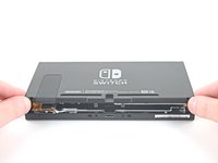
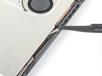
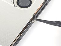
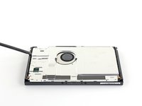
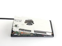
Setze einen Spudger am Rand des Gerätes unter das Abschirmblech ein.
-
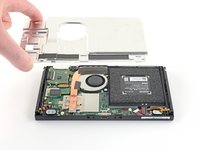
Heble nach oben, hebe das Abschirmblech hoch und entferne es.
-
Wenn du vorsichtig bist, kannst du die rosa Wärmeleitpaste weiterverwenden. Achte beim Zusammenbau darauf, dass sie nicht schmutzig wird und einen guten Kontakt zwischen dem Kühlkörper und der Abschirmung herstellt.
-
Wenn die Wärmeleitpaste ausgetauscht werden muss, dann entferne sie zuerst ganz mit Hilfe unserer Anleitung für Wärmeleitpaste und ersetze sie durch eine geeignete Paste, wie z.B. K5 Pro.
How do you know if the thermal paste needs to be replaced?
Once you remove a heatsink you must always replace thermal paste even if you had just applied it ( or add a little more) . The reason is that once heat sink is fitted, paste splits around because of pressure and only needed amount will remain. If you remove the heatsink then some paste will move so when installed again there will be spots without paste. Hope this is clear enough. In any case cost of paste is very small compared to work time and value of your equipment…..
MacTek -
When your switch starts to lag and drop FPS, if you play breath of the wild and it starts to slow down in heavy areas like the forest where you get the master sword, can i use artic mx 4 insted of the pink compound?
I’d like to know as well if a cpu thermal compound like arctic mx-4 can be used to replace the pink compound
No you shouldn't . It will spill around because it is not viscous enough and then there will be no heat transfer. As suggested by author K5 PRO is the most appropriate compound for such cases.
MacTek -
Arctic is generally only supposed to be used on bigger heat sinks like a personal computer. Its not nearly as thick or gummy compared to K5 PRO, and you should always use something that’s thicker for smaller project like a Switch/phone/tablet.
Why was this not included in the tools/equipment list? Getting to this step and now I will have to reverse and wait for yet another order to arrive. ? Very frustrated
Hi Amanda,
Thanks for bringing this up. Sorry! We inadvertently left that part out during the guide refresh. I’ll add the necessary info into the step.
I agree with Amanda, hopefully I don't lose any parts before I can get the paste. This seems like it should almost be included in this kit from what I've read about this repair. Mine certainly needs to be replaced. I feel like at the very least, this should be at the top of the guide and part order page in bold, red, all cap lettering.
Side note this is the only "issue" I've had of the 4 purchases I've made with ifixit. I recommend you guys every chance I get. I really enjoy doing these repairs with my son.
does ifixit not have an appropriate thermal paste for this step?
there is only arctic silver 5 in the kit and i would guess that that should not be used in this case.
if true, the kit is incompleteSince I couldn't find decently priced K5 I used a 0.5mm thick thermal pad and that seems to have done the trick quite well.
The Amazon link goes to a kit with 6 tubes of K5 Pro. Surely I don’t need 6 tubes… is this kit sufficient? https://a.co/d/5aU8kB7
When replacing the thermal paste, is it possible just to clean the old thermal off the back plate and top of the copper heatsink and just re-apply those areas only, without removing that copper heatsink?
-
-
-
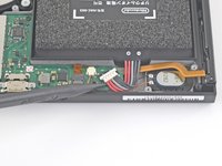
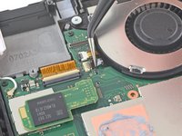
Heble den Akkustecker mit der Spudgerspitze gerade nach oben und löse ihn aus seinem Anschluss auf der Hauptplatine heraus.
be careful not to pry it off the board entirely
This was an old switch and the entire thing with the black plastic came off.. Most of the pins aren't there anymore, too.. is there a solution to that? Does soldering work?
it's probably possible, but unless you have experience with microsoldering, you'd probably be better off taking it to a local repair shop
You can use a spudger to hold down the black plastic side of this connector that is supposed to stay attached to the motherboard while using the pointy spudger as shown in order to reduce any chance of pulling the socket off the motherboard.
-
-
-
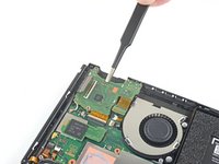
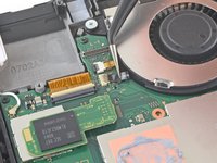
Nimm einen JIS 000 Schraubendreher/Bit oder ein Original PH000 Bit von iFixit und entferne die drei 3 mm JIS 000 Schrauben, mit denen der Kühlkörper an der Hauptplatine befestigt ist.
-
-
-
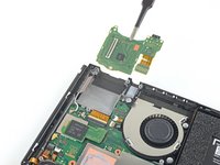
Über den Lüfter und den Kühlkörper sind zwei Schaumstoffstücke verklebt. Ziehe sie vom Lüfter weg.
-
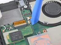
Setze den Spudger mit der Spitze unter den Teil des Schaumstoffs, der nirgendwo festgeklebt ist.
-
Drücke den Schaumstoff oben mit dem Finger fest.
-
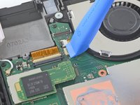
Rolle die Spudgerspitze ganz unter dem Schaumstoff bis zum anderen Ende entlang, bis er abgelöst ist.
Maybe it’s because I’m working on a day one switch and the adhesive is just old and stubborn, but this didn’t work well for me. Am I just completely out of luck, or can I order a replacement for the foam?
I had the same problem and I found a foam manufacturer: https://www.foam-material.com/sample-cus...
I'm pretty sure the type is "Granular Activated Carbon Foam" and the thickness is 0.5 mm but I have no idea what the porosity is.
Yeah ripped the foam. Neither the screwdriver nor spudger technique worked. Day one switch, so 6 years old at this point.
Does the foam need replacing if torn? What does it actually do.
I wanted to know as well, what does it do? Can I replace it with thermal pads?
Can I replace the foam with a 0.5mm thermal pad? Will it be a better solution?
The adhesive remover really helped here being a day one switch
how do you re-glue the foam when putting this back together?
-
-
-
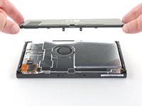
Hebe den Kühlkörper mit dem Spudger oder den Fingern nach oben von der Hauptplatine hoch und entferne ihn.
-
Möglicherweise spürst du ein wenig Widerstand. Das ist normal, weil der Kühlkörper wegen der Wärmeleitpaste an der CPU festhängt.
-
Trage an allen Stellen, die vorher mit Wärmeleitpaste bestrichen waren, wieder neue Paste auf, und zwar auch zwischen dem Kühlrohr und der Aluminiumabschirmung, die Switch benutzt diese nämlich auch zur Wärmeableitung.
What's on the heatsink?
where do i get more of that black fabric like tape that is on the heat sink?
They may sell it in the ifixit store.
(1) Exactly how much thermal paste should be applied to the CPU?
(2) Which application method should be used? The linked instructions list four methods (vertical line, horizontal line, middle dot, or surface spread) but it’s not clear to me which one is appropriate for the Switch. Thanks!
UPDATE: So, for anyone who also wanted to know the answers to these questions:
1. I ended up eyeballing the amount. Imagine an amount the size of a pea, then split that amount in half. That’s how much I used, and it worked fine.
2. The paste (I used K5-Pro as recommended) is quite thick and sticky and difficult to get to behave the way you want, so I ended up just doing the “middle dot” method and spreading it a bit with a popsicle stick before smushing it the rest of the way down with the heat sink. Seems to have done the trick.
Good luck!
Travis -
you can also spread it with the spudger or any non-metalic tool if you are not sure how much you put
just clean it afterwards
K5 (or thermal pads) is ONLY needed between the copper pipe and metal shield plate. It is a pad replacement compound and is not meant for high heat applications like CPUs as it boils and creates air gaps. Air=bad for heat transfer.
Regular thermal compound/paste should be used on the CPU. You’ll have a sticky mess to clean but if you want proper cooling it needs to be done. The instructions clearly state that regular compound is used on the CPU.
Cerus98 -
i used artic silver 5 and worked just fine
The steps doesnt specify but do you have to remove the heat shield from the cpu as well?
-
-
-
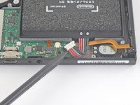
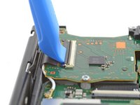
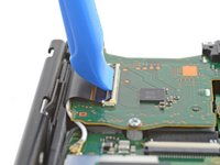
Klappe den kleinen, scharnierartigen Sicherungsbügel am ZIF-Verbinder des Touchscreenkabels mit einem Fingernagel oder einem Öffnungswerkzeug hoch.
This step broke my switch i can't use my card reader anymore! i tried numerous time the reverse it seems my headphone jack works but my touchscreen and gamecard reader is broken. Even worse one of the screws to attach this plate was mangled so i cant even replace it anymore because the screw wont come out anymore. I reallly hate that i followed this guide others suggested to just keep the gamecard touchscreen ribbon attached and just fold it like a book. I wished i did that. I not gonna bother to even buy an gamecard replacement anymore. Its time to buy an switch oled and be done with this!
The advice to "fold it like a book" will not work, as the cable will need to come out of the switch in order to replace the screen. It can not be kept in the slot.
To anyone reading this step: This is not an isolated incident. The loss of functionality of the game reader board, which includes the use of reading cartridges, the touchscreen, and the headphone jack, is an possibility that can happen if you disconnect the board. Unless you are replacing the board itself, do not do this step. As of 1/15/2023, there is no know reason why this happens or no known solution other than buying a new game reader board.
Update: If your Switch has lost the ability to read games and or the headphone jack in addition to touchscreen functionality, please consider reading this thread and its solution: Nintendo Switch Cartridge Reader Not Working After Fan Replacement
it is really hard to see what you need to flip up. look at it from different angles. it's the thinnest little strip of black plastic.
Please help I replace the game card read and head phone. Now my switch wont even turn on.
-
-
In diesem Schritt verwendetes Werkzeug:Tweezers$4.99
-
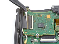
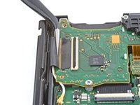
Schiebe das Flachbandkabel zum Touchscreen mit einer Pinzette horizontal aus seinem Anschluss auf der Platine des Softwarekartenlesers heraus.
-
Wenn der Touchscreen nach der Reparatur nicht funktioniert, wohl aber der Game Card Leser, dann überprüfe, ob dieses Kabel richtig angeschlossen ist. Wenn der Game Card Leser auch nicht funktioniert, dann überprüfe stattdessen im nächsten Schritt seinen Stecker.
The reverse of this is a little tricky - it may be helpful to post some more detail about getting the ribbon all the way back in and ensuring the clasp goes down to troubleshoot some of the touchscreen comments below.
This seems to be purely for the touchscreen to work, if you remove the headphone/card reader the switch will still function fine, however without somewhere for this cable to reattach your touchscreen will be disabled
the reverse of this is tricky. i'd suggest a better tool kit with this that includes real tweezers so i don't have to use my wife's
Did you get it to work finally?!
Hi Chris! From the thread, it looks like it's not this connector that's the problem, but the press connector in the step below. If your card reader won't read cards, check to make sure this connector is fully aligned and seated.
This connection was a problem for me. I tried the connection many times before it worked. What finally worked was lining up the gold rectangle on the back of the smaller part to overlap/cover the port very carefully. This required me to compress the ribbon a bit. Not much force required to finish the connection.
I found it much easier to reinsert the ribbon while the reader board was fully disconnected. This way I was able to simply hold the reader board with my fingers and slide it over the end of the ribbon while the ribbon was just sticking up in the air. The ribbon is quite stiff and slipped in VERY easily in such a way that I felt confident that it was fully seated. Then while holding it in one hand, I flipped the locking flap down with a spudger in the other. You might also be able to seat the board and the ribbon will likely stay inserted under its own tension, then flip the locking flap down.
-
-
-
Heble mit der Spudgerspitze den Stecker am Kabel der Kopfhörerbuchse und des Softwarekartenlesers gerade nach oben und löse ihn von der Hauptplatine ab.
Note that if the card reader mentions it won't read cards, this cable has not been reconnected correctly. Watch the connectors are not bent when reattaching
You need to push the connector upwards. Look at the image and you will see a very slight bend. This bent allows the connector to align with its dock. Very very careful when pressing down IT HAS TO BE ALIGNED.
This step had me most stressed during re-assembly. I saw in a video elsewhere where the person reattached the press connector BEFORE screwing it back in which gave them more room to work with. They also pointed out that there's an outline on the top that should line up with where it reconnects. This helped me re-connect with more confidence.
I also reconnected this connector before screwing the reader down. You will not have to contend with the pressure from bending the stiff wide cable leading from the connector.
-
-
-
Nimm einen JIS 000 Schraubendreher/Bit oder ein Original PH000 Bit von iFixit und entferne die drei 3,1 mm JIS 000 Schrauben, mit denen die Platine der Kopfhörerbuchse und des Softwarekartenlesers am Gerät befestigt ist.
-
-
-
Entferne die Halterung der Kopfhörerbuchse mit den Fingern oder einer Pinzette .
-
-
-
Entferne die Platine der Kopfhörerbuchse und des Softwarekartenlesers mit den Fingern oder einer Pinzette.
-
-
-
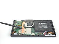
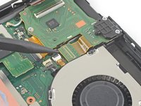
Klappe den kleinen, scharnierartigen Sicherungsbügel am ZIF-Verbinder des Lüfterkabels mit einem Fingernagel oder einem Öffnungswerkzeug hoch.
The little gray tab flew off while I removed the cable. I found it, but I can’t get it back on. Is it possible to install the new fan without it?
No. You will need for professional help to replace the whole ribbon cable connector (ZIF connector).
CCL13 -
I have the same issue, and to make matters worse, my fan isn't working now. I'm not sure if it's a problem with the interface or the fan itself.
argxuy -
A step here is skipped. There is a small board which contains the cart reader and headphone out jack. The connector for the headphone jack will need to be popped off and the board unscrewed. It can then gently be pushed out of the way while leaving it otherwise connected. Reconnecting the headphone jack’s cable is tricky as a heads up. Be patient there.
That step is immediately above this one. Check out step 21 to 23.
CCL13 -
-
-
In diesem Schritt verwendetes Werkzeug:Tweezers$4.99
-
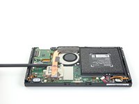
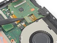
Ziehe das Lüfterkabel gerade mit einer Pinzette aus seinem Anschluss auf der Hauptplatine heraus.
Will need to remove parts and board in top left in order to get to 3rd fan screw.
During reassembly, I found it easier to insert the ribbon from the new fan while the fan was loose and held in my hand. Once the ribbon was inserted and locked down, then I seated and screwed in the fan.
-
-
-
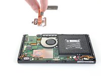
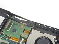
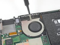
Nimm einen JIS 000 Schraubendreher/Bit oder ein original PH 000 Bit von iFixit und entferne die drei 4,8 mm JIS 000 Schrauben, mit denen der Lüfter befestigt ist.
Petite erreur, il n'y a que 3 vis qui fixent le ventilateur. Merci pour ce très bon tutoriel!
Bonjour @mikaelchola, merci de votre remarque. Je viens de corriger l'erreur. iFixit étant un wiki, sachez que vous pouvez aussi effectuer toutes sortes de modifications. Encore merci et bonne continuation à vous !
-
-
-
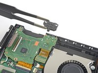
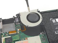
Hebe den Lüfter mit den Fingern oder einer Pinzette gerade nach oben und entferne ihn vom Gerät.
The original fan does not have removable rubber bushings. It has hard plastic ones attached to the fan itself. The original fan is a Foxconn PVB040A05H brushless fan.
Because I cannot remove the brushings but the guide assumes I can, the new fan cannot be screwed in securely, so my repair seems to be failing.
I ended up using 2 tiny regular metal washers per screw and closing it back up. The washers prevent the fan from moving up and down but not side to side. The heat sink probably holds the fan in place well enough that I didn't even need the washers. Either way the replacement fan isn't quite as secure in there as the original. But the repair works -- for anyone else stuck at this step.
Same here. WTF is wrong with this "repair" kit?! I CANNOT repair my Nintendo Switch FFS!
Steffen -
My switch did have rubber bushings that I transferred to the new fan. The old fan was from Delta Electronics.
The fan in my switch did not have bushings either. This replacement kit should be revised to include them.
Come on... The Foxcon model: PVB040A05H-P05 has no rubber bushings. THIS is f*cked up. Now I am sitting with my opened Switch and cannot replace the fan.
My switch had the rubber bushings on the fan already. I took the rubber bushings off the old fan and put them onto the new fan.
I had the same issue with my original being the foxcon fan. I don't recommend it, but I cut the hard rubber bushings out of the old fan using a Dremel or nail tool and then shaped it to the new fan. It was tedious and not worth the effort in my opinion, but it did work
This is profoundly disappointing! I have been relying on iFixit for decades and this is the first time I opened up an entire device in vain because of iFixit supplying a garbage replacement part. My oldest switch had the grommets, but newer models have built in plastic. iFixit could have spent 20 cents on the grommets and I would not have risked damaging a $400 machine on a worthless replacement.
i just used some rubber heat shrink tubing and cut it to size and poked a hole in it.
I didn't have any bushings in my old switch, and couldn't come up with a reasonable "shim". Probably not the best idea but I opted to add a couple small dabs of super glue to the bottom side of the fan to help secure it in location. Hopefully I don't need to remove it in the future.
-


Um dein Gerät wieder zusammenzubauen, folge den Schritten dieser Anleitung in umgekehrter Reihenfolge.
Entsorge deinen Elektromüll fachgerecht.
Lief die Reparatur nicht wie geplant? Probiere zunächst einige grundsätzliche Lösungen oder frage in unserem Nintendo Switch Forum nach Hilfe bei der Fehlersuche.
Rückgängig: Ich habe diese Anleitung nicht absolviert.
231 weitere Personen haben diese Anleitung absolviert.
Besonderer Dank geht an diese Übersetzer:innen:
100%


Diese Übersetzer:innen helfen uns, die Welt zu reparieren! Wie kann ich mithelfen?
Hier starten ›

52 Kommentare
If your joycons are not charging, it could be the fans fault as they seem to share a 1.8v and or 5v rail, I had both joycons refusing to charge, and the fan was not working, so by replacing the fan, it had them charging properly again.
oh? i was wondering why my joycons died and never turned on. i though the hot switch short circuited them. the same thing happened to mine. The fan died as well as my joycons. very useful mate. thanks for the info!
I changed the fan and it still don’t charge my Joycon. What should I do?
baron154 -
I’ve recently found a video that shows what can be wrong with Switch with the same issue, but working fan https://www.youtube.com/watch?v=WuQC3ipu... . In the comments people confirmed several times that it helps.
Andrey -
If I'm just replacing the fan, do I need to clean off/reapply any thermal paste?
It’s always a good idea to clean off and replace the thermal paste if the heat sink is removed.
Definitely, the original thermal paste needs cleaning off and reapplying due to removing the heat pipe. New paste may also improve performance as heat is conducted away from the chips more effectively.
I recommend to do it every time you change a computer fan... It helps to distribute heat better than using the old thermal paste. The cpu will appreciate it
Excellent guide, worked perfectly for me, and I’m very bad at taking things apart and putting them back together. Fan fixed my joycon not charging issue as well.
Thanks a lot. I used this a few minutes ago to fix my little son Nintendo switch (he will woke up tomorrow with this surprise!).
I am not an expert on this kind of fixes and did this with a lot of caution. Took me around 1 hr and 45 minutes.
Greetings from Mexico
Thank you for all the instructions. I ran all the steps, but I was not sure if I put the fan cable properly. In the end, the new fan does not run. Is there a way to test the new fan before closing everything?
Just for future reference, if anyone wants to test their replacement fan that it is able to spin and not by any chance broken out of the box, you can try to hook up a small power supply (nothing stronger than 5V!) to the connector. The connector has four pins. If you orient the fan the way you would put it into the switch with the opening pointing away from you, and we'd call the pin nearest to you pin 1, then the positive wire would go on pin 1 and the negative wire on pin 3. The other pins I assume would be for the control signal that tells the fan how fast to spin.
Here's my setup that I used to test my old (seemingly broken) fan, I used my soldering stand to hold everything in place. Just be aware: the sound you hear in the video is NOT normal, it should be much more silent. This is how my old fan sounded, the noise is what lead me to replace it in the first place.
After replacing the fan according to the instructions (which were easy-to-follow and comprehensive), my Switch now overheats in docked mode fairly quickly. Is there an easy way to determine if the fan is working properly? My Switch is extremely quiet now which leads me to wonder if the fan is faulty or if I just missed a step. I also redid the repair process a second time and took extra care to make sure all the connections were secure, and made sure to reapply the heat paste carefully in each area, including the underside of the shield plate.
This leads me to my other concern: I used the same heat paste applied to the CPU to the shield plate where the thick, pink compound was located. Could it be that I used the wrong paste in that section?
Thanks in advance for the advice.
Completed the replacement, however, now that the fan works, my touch screen no longer is responsive to touch and the cartridge reader no longer reads cartridges. Any help would be appreciated.
Hi Clint! This is a common issue. Try disconnecting the battery, wait ~5 seconds, and reconnect it again to power cycle the Switch.
I am experiencing the same issue as Clint here. I attempted Arthur Shi's solution as described above and it did not work. Has this solution worked for anyone? Please comment if it has. As far as I am aware, no one has come forth and expressed this solution works yet as of January 1st, 2023.
I have the same problem (no touchscreen after replacing fan) and still looking for a solution.
It's a bit strange, since I definitively haven't touched the digitalizer connection cable (wich is accessible only from the front).
If someone have an hint or a solution, please answer :)
TOUCH SCREEN STOPPED WORKING AFTER INSTALL FIX:
This happened to me as well, I found another user with the same issue and this is what (Mark Gentile) said:
"I had the same issue and can confirm it was the press down connector closer to the fan, not the ribbon cable. I put everything back together and had no touchscreen or card reader and started reading all of your comments, fearing the worst. After reading mgrandi's comments above I went back and checked that connector, it seemed seated but was wobbly. The card reader board has a little indent on it's edge, and the press down connector has a little tab. It looks like they should line up, but the press down connector needs to be a bit further toward the side with the card reader slot (away from the center of the switch). It seated more firmly this way and everything immediately worked again."
After following these steps, my touch screen worked again.
Here is the link to the whole post: Nintendo Switch Cartridge Reader Not Working After Fan Replacement
Katie -
For Step 17, do we use the same thick/viscous thermal compound as from Step 13 (the K5 Pro) or can we use a standard CPU thermal paste (e.g. Artic Silver 5) ?
Step 17 does not specify, so any confirmation would be helpful.
As far as my result goes, it is preferable to choose some less watery, more firm thermal compound on both. As long as it does not run around, it is fine to use the same on both. I have not used Arctic Silver 5 so don’t know how that works. But I have used Noctua NT-H1 and Thermal Grizzly Kryonaut, both working well. I’ve tried something quite watery from Prolimatech which quickly stopped working after like a week.
CCL13 -
Fantastic guide. I was able to purchase the fan and the needed tools and replace it without issues. I was able to easily follow the directions to take it apart and put everything back together again. Switch runs silently now like it a fresh new switch. Couldn’t be happier that I didn’t have to try to go out and buy a new switch! Thank you very much for the easy to follow guide.
As a long time computer repair technician, this was about as easy as it comes. I have not touched a console since modding my Xbox 360 with a standard seagate barracuda hard drive in order to play original Xbox games. Excellent guide, easy to follow. Love my IFIXIT Pro Tech Tool Kit and want to thank Steve from @tronicsfix for turning me onto IFIXIT tools and guides.
Is there a different thermal paste I can use instead or can I get a link to smaller amount of the recommended one? I don’t need that much and I cant find a listing for a smaller amount. Thanks in advance!
There's two kinds of thermal paste used originally for different purposes. For use between CPU and heatsink, I recommend something high quality like Arctic MX-4 or better. And the other between heatsink and the shell it could be whatever passable. If you just don't want to stock two variety, use good one for both. MX-4 is quite cost efficient but there are other choices too. 2gram should be about enough.
CCL13 -
Just finished taking everything apart and putting it back together for the second time. Everything seems fine, except that it seems like the switch now has no battery charge, and doesn’t seem to want to charge when connected by cable. Has anyone else had this problem? What should I be looking at to reconnect, or fix, or..?
Thanks
For further information: If I leave it for a while, and try holding down the power button, the nintendo logo comes up for a moment, and then the battery symbol (with a red bar to indicate no charge) comes up. It stay on the screen when the charge cable is in, but doesn’t seem to change, even when I leave it plugged in.
farM0use -
Nevermind…. just needed to charge it for longer. Everything’s working great, and I can only hear the fan when I put my ear right up to it now!
farM0use -
Thank you for redirecting me to the video, it solved my problem.
I have problem after replace fan it work just with full speed all the time. What's wrong? I bought two fans and same problem
I had the same problem, and after tracking down the problem, it turned out that the connector that you plug the fan into was damaged and wasn't holding the cable tightly enough (the fan was getting power, but not the control signal to tell it what speed to run at)
My slightly janky fix was to start the switch with the back off and manually press down on the little connector to get the fan working, and then hot glue the connector in place.
half way threw is enough to get to the fan to clean it mine was making a buzzing noise moving the fan by hand dislodged it
After completing this guide and successfully changing the fan i ran the device and played some games for half an hour without a problem but then a error came on the screen i thought it's just a glitch so i restarted my hacked console and this message came up :
error uSD failed to process the DMA transfert!
error uSD failed to switch to hight-speed from low voltage!
error fatal error failed to initialize the sd card!
I think the sd card reader has problems.
Amazing post. it took me about 1.5 hrs going through each step slowly, but it was exactly as described in this article. THANK YOU!
I followed this guide and replaced my fan in my day one Nintendo Switch. Now my Switch turns on but will not load past the second splash screen.
On top of that I managed to get it to boot Hekate but my touchscreen is completely unresponsive.
It still will not load past the second splash screen when booting stock or CFW.
Tried unplugging the battery to power cycle, as someone else suggested, but even after leaving the battery unplugged for over 30 minutes it is still responding the exact same.
Anyone have an idea what might have gone wrong? Any help would be appreciated.
I just recently replaced the fan successfully. All seemed good, until I docked it and no sound was coming through the tv. I checked the volume of the tv and unplugged/plugged in the hdmi to no avail. Anybody have any idea what I may have knocked around when doing the repair?
You may need to transfer remaining components (such as the rubber bushings) to the new part before installing.
There's nothing like rubber bushings that are detachable from the original fan, but the replacement fan is loose when put in place as a result.
Mine had removable rubber bushings, but I got the Switch at launch. Maybe they stopped using them in later builds. Unfortunately replacement fans seem to need them.
After changing the fan, the switch starts only to the switch logo. Nothing else can be done. I tried as well a hard reset without a result. What can I do?
Got my switch out from the drawer where it has been neglected for years, literally years, my last BOTW save was 2018. Battery at 99%. The fan was making a loud grinding noise so I ordered a replacement and some K5-PRO for the heat spreader. I also had some Arctic Silver 5 for the underside of the heat spreader to make good contact with the CPU. Followed this guide and it was perfect save for a missing bit of foam which the comments said is probably because Nintendo started adding those in after I bought my Switch. Thank you iFixit! You fixed it!
Great guide, seems to have worked perfectly. Just wanted to say that instead of removing the big ribbon on the card reader you can leave it in and just fold the part over the side of the Switch once you've removed the screws and disconnected the headphone connection. Makes things slightly easier.
Great guide. Replaced noisy fan and applied new thermal paste in prep for Zelda TOTK. Highly advise pressing hard when removing 4 screws from back panel to prevent stripping.
Saw some comments concerning the different thermal pastes. Just wanted to share what worked for me:
- K5-Pro thermal paste for the shielding/heat sink (step 13)
- Arctic Silver 5 thermal paste for the CPU (step 17)
The link provided in this article for K5-Pro looks dated/expensive/both, so here’s what I purchased. It should come with a tiny instruction sheet telling you how to apply it, make sure you follow those instructions and try to put at least 1mm even coating of the paste on! Over all, everything went very well, this tutorial rocks. Just take your time, keep the screws organized, and it’s easy breezy.
Oh and one more tip: be firm with some of the screws like on the plastic back panel, make sure you’re using the Y shaped screw driver for that. They can strip easily. I will update this comment thread if anything changes/stops working, etc…
Josh W -
This was perfect, walked me through the entire process with no issues at all. Love the eye for detail in this one.
I followed this guide exactly and with the extra comments included, it was perfect. Everything worked exactly as described. I was able to replace the fan without damaging anything or taking extra parts off the unit. Would recommend this fix 100%
TOUCH SCREEN STOPPED WORKING AFTER INSTALL FIX:
Touchscreen stopped working after installing the new fan. I found another user with the same issue and this is what (Mark Gentile) said:
"I had the same issue and can confirm it was the press down connector closer to the fan, not the ribbon cable. I put everything back together and had no touchscreen or card reader and started reading all of your comments, fearing the worst. After reading mgrandi's comments above I went back and checked that connector, it seemed seated but was wobbly. The card reader board has a little indent on it's edge, and the press down connector has a little tab. It looks like they should line up, but the press down connector needs to be a bit further toward the side with the card reader slot (away from the center of the switch). It seated more firmly this way and everything immediately worked again."
After following these steps, my touch screen worked again.
Link to post: Nintendo Switch Cartridge Reader Not Working After Fan Replacement
Anyway to test the fan after replacement? Definitely not as noisy but battery depleting almost immediately. Not sure if they’re related or not.
Nice guide, just exchanged a very old fan from my first switch and applied new thermal paste while I was at it. Difference of day and night now. Can't hear it at all anymore.
TRY REMOVING CASE SCREWS BEFORE BUYING PARTS
I strongly recommend people try removing the outer case screws before ordering any parts. As many people have commented in the steps the screws on the sides can be extremely tight and appear to have locktite on the threads making them extremely easy to strip.
I found this to be the case with my original Switch and using the ifixit toolkit tools. One came out with care, the other wouldn't budge and is stripping (despite trying the usual tricks)
no rubber guides for fan like in documentation. the guides are plastic and stuck to the old fan. i just used some rubber heat shrink tubing and cut it to size and poked a hole in it so it would remain cushioned inside the switch.
Kann ich diese Anleitung auch für die OLED anwenden? Habe im INet sonst leider nichts brauchbares gefunden.
Ina Barz - Antwort
backup all your sd card data i had to format mine after this tutorial and lost all my game data
JustForThisComment?ComeOn - Antwort
do not watch the video! i broke the metal shielding on my switch because they didn't mention a screw!!!
Macro Man - Antwort