
iPad mini 4 Wi-Fi Display Assembly Replacement

Einleitung
Zu Schritt 1 der AnleitungFollow the steps in this guide to replace the display assembly in an iPad mini 4 Wi-Fi.
Note that if you would like to maintain Touch ID functionality or your replacement part does not include a home button, you should follow the screen and digitizer replacement guide, which includes removing and transferring your home button to the new display panel.
Was du brauchst
Fix Kit
Dieses Kit enthält alle Ersatzteile und Werkzeuge, die für die Anleitung benötigt werden.

Ersatzteile


Werkzeuge


Mehr anzeigen …
-
-
Heat an iOpener and apply it to the left edge for two minutes.
-
-
-
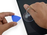
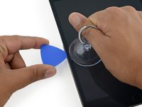
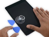
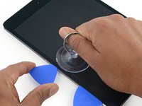
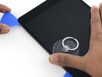
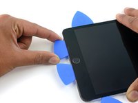
Apply a suction cup halfway up the heated side.
-
Be sure the cup is completely flat on the screen to get a tight seal.
-
While holding the iPad down with one hand, pull up on the suction cup with strong, steady force to create a gap.
-
-
-
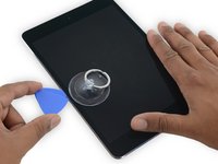
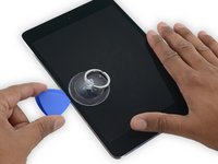
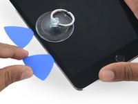
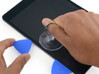
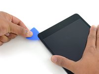
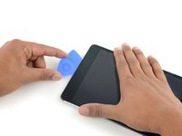
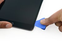
While holding the glass up with the suction cup, insert the point of an opening pick into the gap between the glass and body of the iPad.
-
-
-
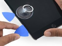
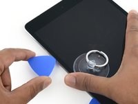
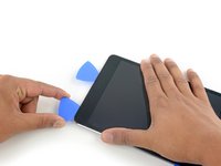
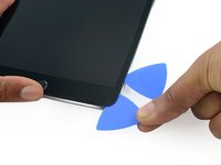
Insert a second opening pick alongside the first and slide the pick down along the edge of the iPad, releasing the adhesive as you go.
-
-
-
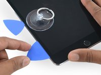
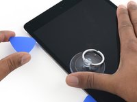
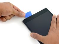
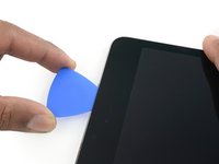
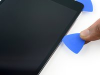
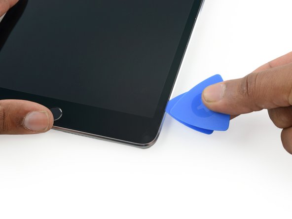
Continue moving the opening pick down the side of the display to release the adhesive.
-
If the opening pick gets stuck in the adhesive, "roll" the pick along the side of the iPad, continuing to release the adhesive.
-
-
-
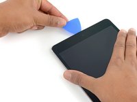
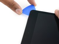
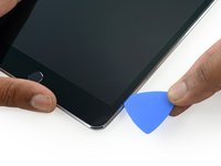
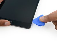
Take the first pick you inserted and slide it up toward the top corner of the iPad.
-
-
-
Reheat the iOpener and place it on the top edge of the iPad, over the front-facing camera.
-
If you have a flexible iOpener, you can bend it to heat both the upper left corner and the upper edge at the same time.
-
-
-
Slide the opening pick around the top left corner of the iPad to separate the adhesive.
-
-
-
-
Slide the opening pick along the top edge of the iPad, stopping just before you reach the camera.
-
As you reach the front-facing camera, pull the pick out slightly and continue sliding it across the top edge.
-
-
-
Leave the opening pick in the iPad slightly past the front-facing camera.
-
Take a second pick and insert it to the left of the camera, where the first pick just was. Slide it back to the corner to completely cut any remaining adhesive.
-
Leave the second pick in place to prevent the corner adhesive from re-sealing as it cools.
-
-
-
Insert the previous pick deeper into the iPad and slide it away from the camera toward the corner.
-
-
-
Leave the three picks in the corners of the iPad to prevent re-adhering of the front panel adhesive.
-
Reheat the iOpener and place it on the remaining long side of the iPad—along the volume and lock buttons.
-
-
-
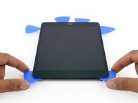
Insert a new opening pick and slide it down the right edge of the iPad, releasing the adhesive as you go.
-
-
-
Continue sliding the opening pick down the right edge of the iPad, reheating the edge using an iOpener if necessary.
-
-
-
Leave the opening picks in place and reheat the iOpener.
-
Set the reheated iOpener on the home button end of the iPad and let it rest for a few minutes to soften the adhesive beneath the glass.
-
-
-
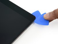
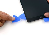
Insert a new opening pick at the bottom right corner of the display, below the last opening pick you used to slice down the right edge.
-
Rotate the new pick around the lower right corner of the device.
-
-
-
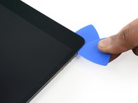
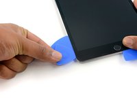
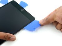
Slide the pick from the bottom right corner along the lower edge of the device. Stop about half an inch shy of the home button.
-
-
-
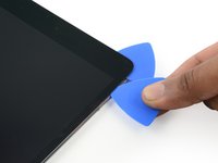
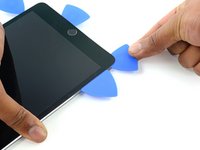
Insert a final opening pick at the lower left corner of the iPad, directly below the existing one.
-
-
-
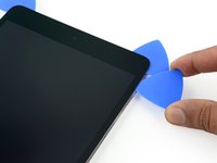
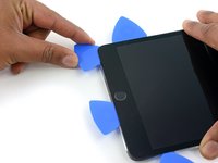
Continue sliding the pick at the lower left edge of the display toward the center of the iPad, until it is roughly half an inch from the home button.
-
-
-
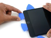
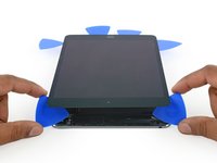
Twist the two picks at the top edge of the iPad to break up the last of the adhesive holding the display assembly in place.
-
Lift the display from the top edge to open the device.
-
-
-
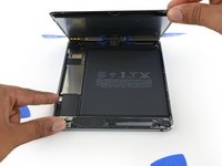
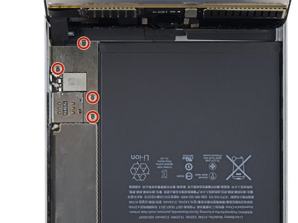
Remove the four 1.2 mm Phillips screws over the battery/display connector bracket.
-
-
-
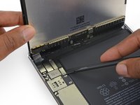
Use the flat tip of a spudger to disconnect the battery connector from its socket on the logic board.
-
-
-
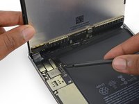
Use the flat tip of a spudger to disconnect the display data connector from its socket on the logic board.
-
Disconnect the digitizer cable connector from its socket on the logic board.
-


To reassemble your device, follow these instructions in reverse order.
To reassemble your device, follow these instructions in reverse order.
Rückgängig: Ich habe diese Anleitung nicht absolviert.
36 weitere Personen haben diese Anleitung absolviert.

2 Kommentare
why after replacement power button doesn’t lock screen, where is those smart cover sensor are located?
great guide but u dont discuss reapplying the adhesive strips .. which is very important.