Einleitung
Erfahre, wie du den Arbeitsspeicher in deinem neuen 2018er Mac Mini erweitern kannst.
Der Mac Mini unterstützt bis zu 64GB RAM - du kannst dabei jede Kombination aus 8GB, 16GB oder 32GB DDR4-2666 SODIMM RAM Modulen benutzen.
Was du brauchst
Einführungsvideo
-
-
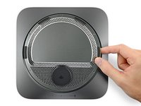
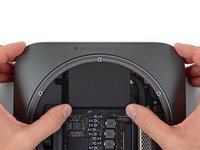
Löse die untere Abdeckung vorsichtig mit einem Opening Tool von deinem Mac mini ab.
-
-
-
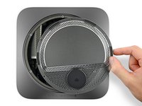
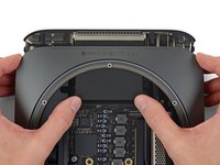
Hebe die untere Abdeckung an und entferne sie.
-
Richte sie sorgfältig so aus, dass du die Schrift "Mac mini" lesen kannst, wenn die Anschlüsse zu dir gerichtet sind.
-
Drücke dann von oben auf die Abdeckung, bis die drei versteckten Klammern einrasten.
-
-
In diesem Schritt verwendetes Werkzeug:Magnetic Project Mat$19.95
-
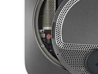
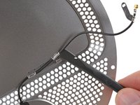
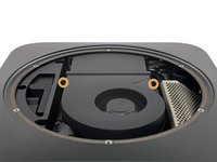
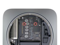
Entferne sechs Torx TR6 Sicherheitsschrauben, mit denen die Antennenplatte befestigt ist. Sie haben folgende Längen:
-
Drei 4,1 mm Schulterschrauben
-
Drei 1,8 mm Schrauben.
Does anybody know the bolt diameter and tread size of the TR6 screws? Eg M2.5 screws? Planning a mod for my MAC mini and will be great if someone knows the exact specs of the screws Apple uses :)
Stripped all of those screws instantly. Anyone know how to fix that so I can finish the upgrade?
The RED screws are Torx T7H and the YELLOW are Torx T6H from their toolkit. fyi.
I used a TR6 (Torx security with the hollowed tip, as per the ifixit instructions) on both the “red” and “yellow screws”, Mini 2020 model.
Also, the red ones had a small amount of blue stuff (thread compound?) around the threads, which made it slightly trickier to reinsert them straight. No big problem though
Make sure you have decent quality screwdriver for the T6 security screws. I bought a crappy one from Amazon that wore out after turning three screws.
Bei mir ging es nur mit einen T7 Torx Schraubendreher (MacMini2018)
This is the third MacMini that I have done some kind of upgrade. The first two were circa 2012. One thing I learned after the first one is to make sure I kept the little tiny screws (LTS) in the right place and segregated for each step of the process. So, what I do now is print the image (from this guide) of the step which requires removal of the LTS and as I remove each one I tape the LTS with a piece of Scotch tape on to the page with the image where it needs to be reattached. It makes it so much easier to reassemble the unit. The time required as listed is a bit understated. I just finished upgrading the memory chips on the 2018 MacMini and it took me one hour and 10 minutes from start to finish. Hope this tip helps.
Intel Mac Mini, purchased June 2021. All screws were TR6 Torx
Intel Mac mini, purchased in April 2021. All screws were TR6 Torx too.
-
-
-
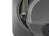
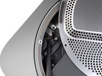
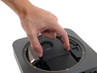
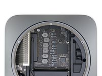
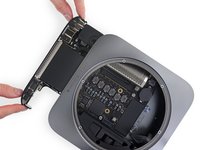
Lege den Mac Mini so, dass die Anschlüsse zu dir zeigen. Hebe dann die Antennenplatte behutsam hoch und schiebe sie etwa 2,5 cm nach rechts.
-
-
-
Entferne die 2,8 mm Torx T6 Schraube, die das Antennenkabel am Logic Board des Mac Mini befestigt.
Interestingly on my Mac mini there was no torx screw holding this on at all, it was just attached to the logic board. There isn’t actually a screw hole to screw it into on the logic board as it appears to be a river of some kind instead.
There wasn’t one in mine either. Wondering if it’s because I bought refurbished. What can be done about this? Is it risky to proceed without one?
Gary -
interesting! mine definitely did - it should be noted that this screw is incredibly small and should be taken out and stored with care
What can you do when you accidentally rip off the connector from the logic board? A piece has become un-soldered and now I have a brick. This was an EXTREMELY, EXTREMELY FRAGILE part. For future folks who are trying this, be extra careful and try to find info on exactly where you should be pulling from. Apparently I lodged my spudger underneath the entire socket where it soldered, rather than above it where its simply connected. It’s very easy to rip the so ket right off the logic board. Now I’m looking for micro-soldering repair places. Do I have other options?
If the 2.8 mm screw securing the antenna cable to the Mac mini's logic board “disappears” and cannot be located after the motherboard is extracted, the screw has propably settled in below the speaker. There is a neodymium magnet in the speaker and it will attract the screw. Loosen the speaker to collect the screw - do not try to push the screw out with a tool as you might do damage to the motherboard. The whole operation of retracting the screw is less than 2 minutes.
Under the speaker is where I found my antenna screw !!
I have only ever cursed Apple a couple of times (as opposed to the several million times for Microsoft!), and this was one of them. That damned antenna screw, putting it back in was a trial of patience and perseverance.
One trick for putting the screw back in is to mount it to the screw driver first. Then wrap tape around both. There's not much screw head for the tape to stick to, but it doesn't need much because it is so light. The tape comes out with the screwdriver as soon as the screw is partially threaded.
-
-
-
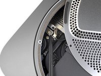
Heble vorsichtig den Stecker des Antennenkabels mit der Spudgerspitze oder einer feinen Pinzette gerade aus seinem Anschluss auf dem Logic Board hoch.
Sorry Ray… I didn’t follow your directions. When I took mine apart, the connector pulled clean off the motherboard. I looked at the icon on the back antenna cover, and it appeared to be a wifi symbol. Not a big deal for me since my Mini is always plugged in via ethernet. So I finish putting it back together… thankfully Mini boots as expected and new memory is registered.
But… everything seems to work fine. Wifi… bluetooth… internal speaker… what antenna is this connector attaching?
I had a similar experience. I finished the RAM install and as I was trying to reconnect the antenna I noticed I pulled the connector clean off the motherboard. I was able to boot the Mac mini and everything seems to be working fine, including Wifi and Bluetooth. I don’t know what the purpose of the antenna is for and I can’t find anything online. I have my Mac mini connected to Wifi and a dedicated ethernet cord just in case the Wifi acts up. It would be nice to know what I broke. I’m just thankful I don’t have a paperweight.
Re-connecting the antenna lead plug was by far the hardest part of the entire operation for me. I found it easiest to roughly position it and then screw the guide in loosely before trying to get plug properly back into the socket. When it goes in you will feel a very slight click. You can tell it is correctly located by comparing it with the two sockets beside it. If it looks like them, then you have it in correctly.
Put the screw into the retaining clip before reseating the antenna cable and screwing it down.
Trying to guide that tiny screw into the right position after the antenna’s plugged back in without it spinning off into the depths of your Mini is an exercise in futility.
Thumbs up on this comment. I had to thread the screw into the hole/slot on the clip, but it stayed seated and it was easy to guide the clip back to the hole that receives the screw.
The cable connector socket is ridiculously fragile. Be extremely careful to apply pressure exactly as shown in the Step 6 photo (zoom in for a better look) — which is to say, on the metal wire clamp away from the connector. I used a spudger, but must have caught the socket on the logic board, because the whole assembly snapped off. Have successfully done this sort of disconnection a number of times on previous Mini models, but it’s far more delicate on this model — access and visibility are limited, so be very careful.
Totally agree with Michael above. Re-connecting the antenna was the most fiddly part of the entire operation. First connecting it and secondly lining up the small guide plate where the screw keeps everything in place.
My tip would be that the connector isn’t particularly difficult as such. It’s just very small.
It is at the top of the cable so line that up. When it is lined up some gentle pushing secures it in place. Definitely don’t try to force it as it looks easily damaged. Like everything, when it’s lined up it’ll be easy and you’ll know it’s all good hearing and feeling it gently fasten.
The screw was easier by comparison. After a couple of attempts the hole was visible enough and it took the screw.
I found it easier to move the antenna plate (instead of the connector) until the connector was over the socket, and then gently push down with my finger until there was a clear click. The same strategy helped me get the metal tab correctly positioned over the hole.
I agree 100%. To remove the antenna was a little difficult. The cable was underneath that heat tube. But for me it was very difficult to reconnect that antenna. It took me long time trying to align the connector. It’s most likely because of the tight confinement of that connector.
Getting antenna back on was the most difficult of the whole operation. Rescrewing connector first helped align the socket.
When I disconnected the antenna, a small foam block popped out with it. What is this and do I need to put it back?
The solder joint broke while I was putting back the antenna. nevertheless I screwed it back on and placed it in the initial position as if nothing had happened. I prayed very hard that it worked.
Well, this had no impact on the quality of WiFi reception. Oo'
I guess I got lucky. This part of the reassembly disassembly is really very delicate. Everything else is a piece of cake.
I slipped a small hook under the cable and gently worked it off. Definitely a little nerve wracking based on the posts here. When placing it back, I also partially screwed the clip down which I believe made it easier to reattach. But still getting the antenna to "pop" back into the socket was tedious and more complex than expected. Appreciate Alex's comment above
So difficult to pry this up. Mine finally came up and took the lil white square insulator with it… hoping it will just reattach to the gold socket nub… oh well 🤷🏻♂️
-
-
-
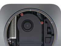
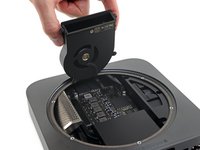
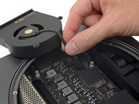
Entferne die vier 7,2 mm Torx T6 Schrauben, mit denen der Lüfter befestigt ist:
-
Zwei Schrauben, die den Lüfter am Logic Board befestigen.
-
Zwei Schrauben mit Gummischultern, die den Lüfter am Lüfterkanal befestigen.
Where are they John, I don’t see two extra, only the 4 previously mentioned
-
-
-
-
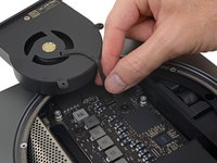
Hebe den Lüfter an der flachen Kante hoch, dort wo er auf den Abluftkanal trifft. Achte darauf, dass das Kabel darunter nicht zu stark belastet wird.
The only scary moment was removing fan from Vent. The two vertical 7.2 mm Torx T6 screws at the top of the fan are easy to remove, in fact almost all of the screws for me were easy to remove because I was careful to get a good lock fit on top of the screws and slowly, while pressing downward just enough to get traction and the screw would loosen. The angular 7.2 mm screws attached to the fan vent with grommets is hard to get a direct angle with original orientation, to get the best lock and traction and use more force as they are very tight. Started to use too much pressure when it wouldn’t move and without direct even tension, I slipped a few times and that always leads to stripping the screw head and your screw driver. Carefully see how they turned the case around, so you can get a better straight angle and once the top screws are off you can gently shift the fan around to loosen the screw grips with the rubber grommets and carefully unscrew .
Note here in the photo that you can see that the fan is taller than the enclosure (it extends above the metal “rim”). When I was reassembling I inserted and removed the fan three times assuming that I had mis-aligned it somehow!
-
-
-
Fasse das Lüfterkabel an allen sechs Drähten an und hebe es vorsichtig hoch, damit es sich aus seinem Anschluss auf dem Logic Board löst.
Uh-Oh, me too… Really gently lifted off the fan connector and the socket came off the board.
The six pins that hold the socket to the board are incredibly close, and if this happens to you I strongly recommend you take it to someone who’s been soldering since before they were born, and knows exactly what they’re doing, to fix the socket back to the board.
It’s taken me two days (buying a decent soldering station etc.) and my ears hurt just as badly as the appendages between my legs, because the Mrs is extremely disappointed!
Suggestion for iFixit: please show this step in more detail, and warn everybody just how easily the socket can come off the board (please and thank you). Good luck everybody.
This use to happen to me when upgrading 2012 mac mini’s. Have to use a spludger or something to hold connector down while you pull it upwards, flipping lightly on back of cable. it clips in, so don’t try to”plug” or insert.
When putting the fan back, step 10 should come before step 11, no?
So …12, 10, 11, 9, 8…
Same here. Socket is broken. I really wish I hadn't tried to this because now I have to take it into a shop anyway.
There are two metal prongs near the wires that seem to lock the connector in place. Wiggling these a tiny bit with tweezers may help loosen them up. Press the edge of the connector furthest from the wires against the board with a spludger while pulling up gently on the 6 wires. The connector seems to sort of roll out of the socket towards the port end of the mother board.
Used the pry under the wires to wiggle it loose. Good luck!
-
-
-
Entferne den Lüfter.
When putting the fan back, step 10 should come before step 11, no?
So …12, 10, 11, 9, 8…
-
-
-
Fasse das Kabel der Stromversorgung und hebe es hoch, um es vom Logic Board zu trennen. Wackle unter Umständen ein wenig daran, um es abzulösen.
Loosen the side nearest outer case first
It appears there are curved metal tabs (1 on each side of the connector) that compress until they lock the connector in place or the connector is removed, but doing so evenly as to not break off the 2 gold knife blades on the logic board that slide into the plastic connector. Both the tabs & gold knife connectors are seen in the 2nd picture, in the first picture you can see how the tabs look when they are locked into the logic board connection.
-
-
-
Hebe vorsichtig den Stecker der Status-LED gerade hoch und löse ihn aus seinem Anschluss auf dem Logic Board.
So I followed the picture above, but lifting straight up on it ended up breaking off the entire component from the board…
Is there a way to fix this? It doesn’t look like the computer turns on without this connection made
@ksmoran Yes, it can be fixed. See Maarten’s comments on the RAM guide. That connector is only for the LED indicator light on the front, so your Mac mini should still turn on and work fine. If it’s not turning on, there’s some other problem.
I have also broken the led connection off the logic board. Is there another way to reattach it, other than finding someone to solder it?
The video at the top of the page (timestamp: 2:30) does a much better job showing how to do this. They didn’t use any tools. Simply use your fingers to pull the wires straight up from the connector. Don’t try touching the actual components, since they’re so fragile. The wires are the better bet.
I found it easy to get the corner of a plastic spudger underneath the wires as close to the plastic clip as you can get it, and gently prying up. Use the logic board as the base for prying. Didn’t take much force, and everything here is really delicate. I’d try a plastic spudger here first.
This worked for me, and didn’t take a lot of force.
thanks that worked nicely
Ditto on the spudger- i couldn’t shift the connector with the angled forceps as shown in the photo
I also used a plastic spudger.
I think I broke something here, too. I was able to disconnect it and reconnect it. But the LED does not light up anymore. I will not open the device again to fix this. It also works without the LED lighting up.
I’m a proud new owner of a perfectly functioning, 3 GHz 6-Core Intel Core i5, 512GB SSD, & 32GB RAM(came with 8GB RAM), 2020 Mac Mini with a broken LED connector. I thought I was being so careful lifting the LED wire off of the socket, but that little socket is fragile, very fragile. So, no, I’m not worried about the LED working. It’s entirely in stealth mode now, not drawing attention to the nearest passerby. I do wish I hadn’t broken it, but it’s so much better than “bricking” it!
It appears there are curved metal tabs (1 on each side of the connector) that compress until they lock the connector in place or the connector is removed, but doing so evenly as to not break off the 2 gold knife blades on the logic board that slide into the plastic connector. Both the tabs & gold knife connectors are seen in the 2nd picture, in the first picture you can see how the tabs look when they are locked into the logic board connection.
Do not lift anything at all. The wording above talking about a connector is misleading There is no connector as for the antenna cable. These are two separate cables plugged horizontally into the socket on the logic board. You need to pull these cables horizontally out of the socket. Do this carefully and slowly best by using tweezers gripping the cable or metal cap as close as possible to the socket. Once I figured this out, the cables came off quite easily.
I’m sorry to disagree, but there is a connector, similar to the one for the fan (but much smaller, and more fragile). Do not pull the wires out of the socket! Best tip was to use a spudger to gently lever under the wires near the connector so that it pops up vertically.
I attempted and failed at following these suggestions. When lifting up didn’t work, i tried to pull horizontally as suggested by Walter Jury. Unfortunately, I pulled the two wires from the connector, leaving the connector on the board. After the memory swap and reboot, i may consider a fix to the led light.
I also used the spludger. The flat end and just a little at a time to make sure I didn’t get the connector on the motherboard
There are two metal prongs near the wires that seem to lock the connector in place. Wiggling these a tiny bit with tweezers may help loosen them up. Press the edge of the connector furthest from the wires against the board with a spludger while prying gently under the 2 wires with another spludger.
-
-
-
Drehe die beiden 7,5 mm Torx T10 Schrauben heraus, mit denen das Logic Board befestigt ist.
Yes - Had to use a pliers to turn the T10 Screwdriver to get the first turn loosened!
Yeah, very tight. Make sure you put your strength into the twist and not the press. This made all the difference for me.
The second screw just wouldn’t come out for me!
Note that these are T10s, not TR10s. I also had trouble with how tight these were, too. I even started to strip the screws with the iFixit TR10 bit and driver. Luckily I did the smart thing and quit the brute force+ignorance route. After a quick trip to Canadian Tire, I used this folding set of Torx drivers to get the screws out effortlessly.
Glad I wasn’t the only one. I didn’t have much around me but a paper towel helped me with the grip and I was able to get it off
what they said above. these two T10 screws were hard to unscrew!
The tightness is just caused by the blue stuff they use to seal the screw in the hole (presumably for warranty purposes). As koopsmooth says, put your strength and speed into the twist and not the press so that the seal snaps.
Almost impossible to remove with the iFixit tools (replacement kit). Felt like I was damaging the screws. Twisted right off with a regular screwdriver with T10 bit.
Embarrassed to admit that I was trying to remove the logic board, couldn’t do it, and then realized I had only removed one screw :(
Suffice it say that it came out pretty easily with both screws removed.
-
-
-
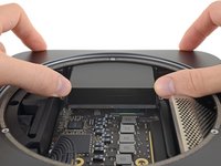
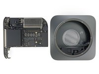
Setze die Daumen an jedem Ende des Abluftkanals über den Schraubenlöchern des Lüfters an.
-
Drücke fest in Richtung der Anschlüsse, bis sich das Logic Board löst und das Logic Board aus dem Gehäuse herausgleitet.
Okay - I used a lot of “might” to push on the ends of this heatsink to no avail. Literally, I was scared to break it - I could feel one side moving and the other not budging. I used a large flat-edge screwdriver vertically into the Mac Mini, prying lightly against the edge of the case hole and onto the back edge of one of the silver fan standoffs protruding from the motherboard. Very little leverage here caused the board to pop out past those tight clips. Phew!
It does take a lot of force. I found the best way to handle it is to put the two exhast screws back in and use two T6 screw drivers to push. Thats easier than using your big thumbs and keeps you from damaging the fins.
Wow, great. Thanks for the comments above, and mine is also very difficult to push. I screwed back to two T6 screws and is still no luck. At the end, I push the two screws with a T6 screwdriver and bang, much much easier. Just my two cents. Good luck guys.
Watch your fingers pushing this out! I just cut my thumb on the sides
Got myself sliced on the right thumb. Don’t even know on what.
A few people have commented here about having to use a lot of force to get this out, but make sure that all of the black area at the back of the case are not being covered by your fingers as you try to push it out, it came out quite easily for me once I realised I had my fingers on it!
This may sound really stupid, because I am :) but keep in mind that the logic board assembly is coming out the side. So as you push from the inside don’t be blocking that motion with your fingers on the outside of the case. Once I realized I was defeating my own pushing of the fan it came out very easy.
Mine came out as described. Did not need “too much” force
Duh. I put 8 fingers on the back of the case, and two thumbs on the exhaust vent and SQUEEZED. Wouldn’t come out.
Then I read the comments and realized my thumbs were pushing against my fingers. As soon as I moved my fingers, it slid out with no effort.
I positioned the case on my lap so that I could get my hands under and around the side of the case, with just my thumbs inside. It came out effortlessly. Before that I tried sliding it out with the Mac on my workbench and it wasn’t moving.
WATCH YOUR RIGHT THUMB!
Do not put your right thumb in the position displayed in the 1st diagram!
When I exerted force to push the board out, the RAM guard sliced my thumb open in the exact point where the thumb is contacting the RAM guard. Since it’s hard to know how much force to exert the 1st time, you may end up like me.
In the 2nd and 3rd photos, you’ll see how the thumbs are positioned above the RAM guard - this is likely a safer position.
Pretty embarrassed to admit that I tried removing the logic board with one screw still in place. Once removed the board came out pretty easily.
This can be done without any pushing.
Use momentum and gravity - hold it so that gravity pulls the insides down and then use your hands to "hit" - in turns - left and right side in the "up" direction (momentum keeps the insides in place while the "hit" causes the shell to move up).
You are all wrong!
There is a small hole on the right bottom side when the ports are facing you. Use a small screwdriver, put it in the small hole to unlock the snap-in bracket on the back, and the right side will lock out of place and pop out on itself.Then you can gently push the logic board out of the Mac Mini without the chance of damaging it.
Can't believe nobody caught on this. -
-
-
Schiebe das Logic Board aus dem Gehäuse.
When sliding back INTO the case after you’ve replaced the RAM, be sure to keep an eye on the LED light indicator connector cable. It’s easy for the logic board to slide back in and cover up the cable, which risks breaking the plastic end piece.
Tape the LED light indicator to the case to keep it out of way until reassemble.
Also make sure the power cable connector does not slide between the power connector on the logic board and the big capacitor (marked 101) when sliding the board back into the housing.
-
-
-
Entferne die vier 2,8 mm Torx T5 Schrauben, mit denen die RAM Abschirmung befestigt ist.
T5 worked for me. No TR5 was needed, thankfully.
Just had to recognize that you should be careful with the screws on the left side, when you drop them accidentally, the little magnet of the speaker might catch them an they tend to stick below …
For my Mac Mini 2020, I used a T5 Torx. The T4 fits but is a tiny bit loser.
-
-
-
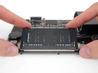
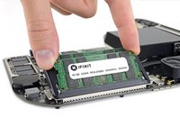
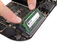
Jedes RAM Modul wird auf beiden Seiten von zwei Klammern festgehalten. Drücke die Klammern mit den Fingern vom RAM Modul weg.
While spreading the Clips with the Rubber away, the right one just popped off. To reattach it, I had to slide it on the metal clips from the top.
The ‘rubber’ side guards should be slid off and removed. The guards and cage are designed to prevent movement and loosening of the RAM modules when subjected to shock and vibration. Removing the guards allows the free movement of each RAM insertion mechanism. The guards are designed to then lock the RAM units together in the same orientation once installed. Use a torch and magnifying glass to see how guards attach into the top of the spring clip arms. The two RAM clips must be re-connected to the guard simultaneously at the same angle.
-
-
-
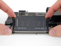
Schiebe jedes RAM Modul gerade heraus und entferne es.
-
-
-
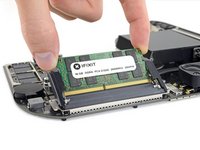
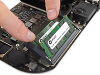
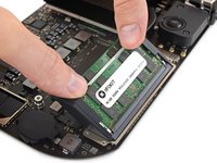
Achte darauf, dass das Modul richtig orientiert ist und der untere Einschnitt passt. Schiebe es dann im gleichen Winkel wie beim Ausbau hinein. Drücke gleichmäßig, bis die Goldkontakte nicht mehr sichtbar sind.
-
Wiederhole das Ganze für das zweite Modul.
If the rubber covers come off they are a pain to put back on - you have to slide the rubber into space between the RAM module and the retainer clips - this video explains it perfectly -
Thank you, you're the hero I needed today. This step was the only thing holding me back.
Had the same issue with rubber guards. See my comment on Step 22.
Also, found it quite challenging to avoid touching the gold connectors. Not so much on removing the old modules but tricky to avoid touching whilst inserting the new.
that video also shows the memory being removed and reinserted once the rubber covers are off — I found it a lot easier to remove the covers in order to insert the memory, and then re-seat the covers once installed.
My upgrade went just fine, but at this point the iFixit sticker was facing the opposite way. Just make sure the notch at the bottom is aligned - that’s the most important part. You might need to have the module facing the opposite way than the picture there.
“Press evenly until the gold contacts are no longer visible.”
I put it back together with just a little bit of gold still visible. I should have known because the clips didn’t feel right and the RAM shield was too snug. Wouldn’t boot up, so did it over and made sure no gold was visible. Clips fit much better, shield slipped on easily, and it now it works.
The rubber covers just need to have the the small guides inserted into each bracket and it slides right back on.
-
-
-
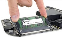
Wenn die Gummiführungen dabei die Halteklammern stören, dann drücke sie mit einer Hand vom RAM weg und bewege mit der anderen Hand das RAM an seinen Platz. Lasse dann die Führungen los.
I’m having trouble with either bad RAM slot or damaged SLOT. Does anyone know how the Slots in the GUI (1 and 2 ) match up with those on the board (A and B)? Link to picture of the GUI and Board for illustrative purposes.
By this point, the rubber guards had completely fallen off and were proving troublesome to fasten back into place.
Eventually, on careful inspection I realised my error. The rubber guards on the inside have thin needle like rubber inserts that actually fit inside the metal RAM clips. Inspect one of them carefully on the inside with a magnifying glass and you’ll see what I mean.
So, to re-attach, angle them with the RAM and retaining clips. Next slide them down at that angle such that the thin rubber insert enters the top gap of each retaining clip.
ps. just seen a similar comment on this and a video posted on the previous step by @dermoid777.
i found it easier to get the memory in with the rubber guards removed
The rubber things came off for me too. This should possibly be another step in this instruction set
Agree with the comments re rubber guards. Also, fitting the new memory into the clips is not that straightforward either. Being used to just slotting memory into main motherboards this, by comparison, was rather fiddly and frustrating. Sorted in the end though but I have yet to test!
Would also add that one of the ram guard screws went awol for a while after flying out of my tweezers. I guess it wouldn’t really have mattered to lose one screw but finding it, after several minutes of searching, was a relief.
I definitely recommend removing the rubber guards entirely whilst seating the new RAM - they obstruct the view if not and make it more difficult to work on a single slot at a time.
Also make sure that the new RAM is inserted at the right angle to ensure it drops down fully into the slot - you’ll know when as you’ll see the holes in the bottom corners of the RAM module line up with the pins on the retaining clip.
Question: Does it matter if you don't put the rubber guards back?
Yes, you need the rubber guards, they serve as the mount for the metal RAM shield.
UF Gator -
-


Um dein Gerät wieder zusammenzusetzen, folge den Schritten in umgekehrter Reihenfolge.
Entsorge deinen Elektromüll fachgerecht.
Die Reparatur verlief nicht wie geplant? Schau in unsere Community zur Fehlerbehebung.
Um dein Gerät wieder zusammenzusetzen, folge den Schritten in umgekehrter Reihenfolge.
Entsorge deinen Elektromüll fachgerecht.
Die Reparatur verlief nicht wie geplant? Schau in unsere Community zur Fehlerbehebung.
Rückgängig: Ich habe diese Anleitung nicht absolviert.
385 weitere Personen haben diese Anleitung absolviert.
Besonderer Dank geht an diese Übersetzer:innen:
100%


Diese Übersetzer:innen helfen uns, die Welt zu reparieren! Wie kann ich mithelfen?
Hier starten ›

151 Kommentare
No, the CPU is soldered to the logic board.
https://www.youtube.com/watch?v=2UrSLnnM... complete RAM upgrade video
Looks like the SSD is replaceable as well. Any idea on what kind of standard it follows?
looks like soldered to me. either way, with that T2 chip on board one shall not pass through…
How many slots for ram rank have Mac mini? And the entry version (8Gb) how many rank have ? One of 8gb or two of4gb? Tank’s
There are two RAM slots.
If you order the Mac Mini with 8GB RAM, it will contain 2 x 4GB RAM cards.
what about the CPU??? Please explore more!!!
Hi Peter,
the CPU is not socketed. Check out the teardown here.
Can you put 2400Mhz RAM in the Mac Mini?
I ask because the MAC mini memory ram is rated for 2666mhz and I have ddr 4 2400mhz RAM laying around.
I’m curious to this as well, because performance-wise there’s not any noticable difference but there is a price difference.
Mikael D -
I had a pair of G.Skill F4-2400C16S-16GRS laying around as well and both went in to an i5 mini no problem. About this Mac reported that the new memory speed was 2400 .
Ben -
Is it possible to have :
1x 4Go DDR4 Apple 2666Mhz
with
1x 16Go DDR4 Crucial 2666Mhz ?
Yes, you can mix and match the module sizes in just about any Mac, so you could even have 4GB +32GB
Rod, do you know if the performance is affected by different sized RAM? It may be too late for me now, but maybe I should have bought one 32GB module instead of two 16s.
Although it is technically okay to mix ram sizes (if the mobo and BIOS allows it), there IS a performance penalty when not using matched pairs of memory. That is true for just about any computer (Windows PC or Mac); , it has to with interleaving and other factors. In some cases, even if both sticks are same RAM size but different makers or configurations, that can also cause a performance hit, hence why most recommend using matched pairs of SAME manufacturer / model. By configuration i mean a 4 GB chip may have a 4 x 1GB config., where as another 4GB chip from another maker may have a 2 x 2GB config or 8 x 512MB (or whatever, ) Macs have historically much tighter tolerances (ie. less forgiving) when it comes to memory vs say a garage mix and match PC build; I strongly suggest using matched pairs by same maker, and stick to reputable brands. there are a lot of gray market chips out there with very questionable tolerances; if the price SEEMS TOO GOOD, THERE IS A REASON.
No it will not brick the mac, worked like a charm with the Corsair 2x16GB from Amazon. Sorry IFIXIT.
Provided you take static precautions and use general care.
This tutorial is a great step by step. I used the IFIXIT TOOLKIT and the IFIXIT Magnetic Project Mat to complete the task. 30 minutes start to boot up. Save about 350 some odd dollars versus ordering it preconfigured from Apple, but to each their own.
32GB RAM should meet my needs for a while, as it has for several years now. I read that the mini won’t be as fast with unbalanced RAM, so I ordered 2x16 instead of 1x32. That could have given me 36GB along with a 4GB from my 8GB mini order. 2x16Gb costs less than 1x32 so there’s a savings there, but I will ultimately have wasted money on the 16GB SODIMMs if I eventually need to upgrade to 64GB. Wasn’t an easy thing to decide on.
Lots of people will face this dilemma.
You should have gone with 2x32
As I wrote the previous post on the 8GB mini, the security bits for installing the RAM arrived. With 8 programs and several background processes running—the LG 4K monitor Newegg had on sale last week for $259 has 30 icons on its menu bar—the mini is still comfortably below its 8GB limit. With paging occurring only infrequently and at blazing-fast speeds, I’m beginning to wonder if I’ll ever feel a need to install more than 32GB RAM.
Now to get to work and put those tools to use. Thanks for the tips!
Thanks so much for putting this guide together! Upgraded with 32GB of Crucial RAM. It works great, and I saved $240!
Bricked! Mini will not turn on. Any ideas?
For the avoidance of doubt. I presume I did something wrong. Anyway, put factory ram back in, still doesn’t start.
Have you tried unplugging everything except a single monitor, keyboard, and mouse from the Mac Mini? I had some issues starting up the Mac Mini with a lot of peripherals plugged in. It seems to have resolved itself after it fully loads for the first time and all the updates hit. Although it does worry me a bit, long-term.
That comment probably just saved Apple thousands of dollars lol. Hope you got it fixed, please keep us hesitants posted.
I tried both removing all devices (headless) and just the basics. Is there anyway to tell if the power is plugged correctly to the logic board? I mean it looks right, just trying to think of things I could check. The only things I can think of are that the ram is somehow out of alignment in some micro way, (i tried new ram, old ram, wiggling in various directions etc) I didn’t put the power plug back on the logic board correctly or I somehow fried something..
spamsea -
One other thing you might try is powering it on in Recovery mode to confirm there is no software glitch. Have you posted this in the Answers community? There might be more technical folks there to try and help.
Did you get it working spamsea?
I had heard that it was necessary for Apple to run some sort of hardware test before new Apple products would be able to run ANY replacement parts. Could this be the reason it doesnt work? Now I’m nervous about trying to upgrade.
Same-ish here. I swapped out the original ram for 32GB (2x16) from Crucial. Then the Mac mini won’t turn on again. I put the old ram back in and it turns on, but only recognizes one slot.
Jarrod -
Well, there is nothing for it, just gotta take it in to the Genius Bar. See if they can tell me what is wrong.
spamsea -
I’m bailing on the upgrade, it’s just not worth the potential hassle. And I thought about it, if ever I need to take it in to Apple for repairs during the apple care warranty, that’s opening and closing it 3 times, RAM in RAM out, might get away with it once, but opening it 3+ times ups the chances to break something.
Fixed it.
Problem 1: The ram wasn’t seated properly. It clicks into place a few millimeters before it’s pushed down far enough. Push until the gold connectors are no longer visible at all. Mine seemed like it would break, but it didn’t.
Problem 2: This one was minor, but I had to hold the power button down for 5 or 10 seconds before it turned on. This isn’t usually the case, it’s only after replacing the ram.
Jarrod -
Way to go Jarrod! Thanks for the update. Please post another in a day or two as to how stable everything is. Thanks!
Jarrod - are you still experiencing the power button long hold to start?
Second mini. I followed the same steps, it all went fine. One difference is that on the second mini, I replaced the ram before turning it on for the first time.
spamsea -
This goes to my comment that Steps 19 - 22 and in Step 22 in the comment it says currently:
If the rubber guards interfere with the clips, spread the rubber guards away from the RAM with one hand and use the other to angle the RAM modules into place. Then, release the guards.
This should be replaced with - Remove the rubber grommets or RAM SHIELD FEET by sliding them in the same direction you slid the RAM SHIELD to remove it and then replace the ram normally. Replace the FEET and the Shield as described.
Info: Mac Mini 2018 also works with DDR4 2400 Mhz
About this Mac: https://gyazo.com/b203d435cf809b2775abb7...
System Info: https://gyazo.com/21213acd745d5f2d6219c3...
Looks like we have a wait a little while more before we proceed to change those RAMs. The worst fear is bricking the whole system.
Let’s wait for more updates from those who can’t turn on their systems after changing their RAMs.
Plus, if the MM 2018 is able to run various task normally at 8GB of RAM, I don’t see myself upgrading the RAMs until the pricing are much lower. For now, 64GB is about $1,080 at OWC website which is ridiculously priced! Maybe when the MM is able to accept and run 128GB worth of RAM (day dreaming at the moment!), I will buy it! Will only purchase the 64GB RAM when it is less than $500 or less. My take for those who have not upgraded yet, use your MM for now and don’t think of upgrading your RAMs until much later. Upgrading to 32GB will see some improvement but why not wait a couple months and get the 64GB which will max out your system. MM 2018 is still relatively new and iFixit probably need to go through the whole system again to see and retest to make sure whatever we open, will not void out 1-3 years Apple Care Warranty plus brick the whole system.
Yes, anxious to hear how upgraded Minis are working.
What, no antistatic mat and bracelet. If the RAM modules are sensitive to static charges, you should use static protection gear. You can zap a memory chip and never even know you did it until you cannot boot or you get system crashes or other oddnesses.
Thank you for your guide.Great work. I added 2x16GB Crucial and it’s working like a charm. One drawback … I killed the WLAN antenna socket. This one is very very fragile. While putting the cable back on the pin and pushing gently to lock it the whole socket came off. Good that I don’t need the WLAN module and maybe I’m able to buy a new socket somewhere sometimes and solder it back on place …
Hello. Is it possible to run the Mac Mini 2018 with only one RAM module (leaving the second one empty)? If it is possible, is there a penalty in its performance?
Thanks you.
This is the first ifixit repair guide I’ve ever followed. The 3 steps I was most worried about...Step 6: antenna cable connector removal. Step 10: fan cable removal. Step 13: LED indicator light cable removal...weren't an issue at all. In fact the only step I had an issue with was Step 15 (pushing the logic board free) and that's because I wasn't pushing hard enough. Overall, a little scary to crack open something brand new that's $1k but I was able to pull it off without issue. (thankfully). Now this Mac mini is running with 32GB + 3 monitors and should last me the next 4 years till Apple updates it again.
My upgrade went pretty much okay. Easier than I thought. Antenna wire snapped right back on, motherboard slid out without much effort and memory modules were easy to remove and seat. Only problem I had was a stripped head on a fan Torx T6 screw on reassembly. I must not have had the driver seated into the screw correctly. Screw is tight so all okay for now. Booted up and shows the 32GB of RAM. Need to find a new screw and hope the old one comes out. I know I didn’t crank it down. Any idea where to find that screw?
Yes that angle of attack should probably be emphasized in detail in Step 8 - good point!
I was like WHAT? Thankfully I have my cheater glasses (old eyes) and I was able to see the angle of attack clearly under magnification.
Step 8 - make it more clear the ‘rubber grommeted’ screws are ‘captive screws’ and they are specifically the yellow screws holing the front of the air box to the heat sink - not the red screws which are removed completely during this process.
Step 15 - for me it was necessary to use the blue pry tools employed in the opening of the bottom cover to assist in ‘freeing’ the main board from the housing - probably not everyone will encounter this but after some serious pushing on the heat sink without result, I fell back to this step. I pushed and the left side budged, but only slightly. So I started on that edge at the ‘case / port mounts of the mainboard seal’ with the blue pry tools and boom it popped free and I was able to complete the step as described to free the mainboard completely from the case…..
Step 19 - 22 I think it should be made clear that there are rubber grommets that serve at the ram shield ‘feet’ and they can be remove by sliding them in the same direction you slid the Ram shield to remove it. then you can replace the ram - replace the ‘rubber feet’ and then the Ram Shield. I preferred this method to ‘fumbling around that rubber to access the clips to free the ram. This step should definitely be included.
Great tutorial - easy to follow - thanks man!
Hi Rod,
On Step 3 it says to “Remove six TR6 Torx security screws…of the following lengths: Three 4.1 mm screws; Three 1.8 mm screws”
Is this a typo? How can it be that one TR6 screwdriver can remove two different sizes of screws/
Thank you for your help.
Ken,
It is not a typo the screws are different sizes but require the same T6 Torx to remove them. The Larger serve as the mount points for the rubber case bottom and are in fact what you used the pry tool in steps 1 and 2 to remove the bottom cover ‘from’.
Hope this helps.
Roger
TR6 is the head size, which is shared by both screws. The millimeter measurements are the lengths of the screws from head to the bottom of the shaft, not across the width of the head.
This guide is excellent. I would have been stuck at removing the logic board without it! Sure glad I bought the iFixit toolkit on Black Friday. What I installed was Ballistix Sport DDR4-2666 (2x16GB). But Mac reports it is running at 2400MHz, not 2666. Otherwise it is working great. Has anyone been able to correct RAM speeds? On a PC I’d fiddle with BIOS settings and kick in the XMP profile, but is there anything I can do on a Mac?
Unfortunately I &&^&@@ up on step 13.
I was afraid to pull on the LED wire and had no grip on the plug. The I tried to wedge with a knife from below and the whole socket including the plug came loose from the board.
I know now this was stupid! Probably I should have lifted on the wire itself, right?
Do you think the tiny connections from the socket can be soldered again by somebody more professional?
@sikko Highly likely it can be fixed by somebody with the right skills and soldering rig. Fortunately I believe that socket is only for the little indicator LED on the front, so it’s likely not a mission-critical item. You can probably put it back together and ignore it. If I could pick one thing to break, that would be it ;)
@sikko Highly likely it can be fixed by somebody with the right skills and soldering rig. Fortunately I believe that socket is only for the little indicator LED on the front, so it’s likely not a mission-critical item. You can probably put it back together and ignore it. If I could pick one thing to break, that would be it ;)
Jeff Suovanen - 2 hours ago
Yes Jeff, I put the mini together yesterday and found that everything was working okay (with 32 GB of RAM) except for the LED light. Today I went to an electronics repair guy, who soldered the socket back in place. That made me happy again. He was professional and really nice guy and did not even charge me anything for this soldering of the LED socket! So fortunately all is fine again.
I noticed now there is a warning at Step 13. Very good! I don’t know if that warning was there yesterday; at least yesterday I did not notice it.
Excellent description! And with the tools from iFixit it was easy to upgrade my MacMini 2018 to 32GB RAM. Thanks a lot.
Completed upgrade this evening. Great instructions!!!
Thank you Rod! Did a successful memory upgrade from 8Gb to 32Gb with this step-by-step guide!
Excellent guide!
ironically I found the 2018 model much easier to breakdown than previous models.
One thing to think about regarding memory and the fixed internal storage. 8GB while sufficient for most light duty users still causes some swap activity to write back to the main storage. While SSD/Flash based storage life-cycle has proven to be extremely durable, continuous swap activity does consume some of the finite write cycles for the chips. With older/slower physical drives this was usually an after-thought.
Additionally, storage failure in any way now requires logic board replacement versus a separate drive swap. Lastly, if failure does occur, what mitigating factors does Apple (or any authorized service agency) take to ensure personal/private data is completely destroyed? Non-fixed drives don’t have this problem - replace the defective drive and load back up, assuming the consumer retains the original drive.
Hi all, does anyone know the details of the little two pin led connector? Whilst removing it during a RAM upgrade one of the wires pulled through the plastic housing of the connector. The board pins are ok just the housing of the connector and I’d like to replace it. Thanks.
Thank you, Rod!
Excellent step by step tutorial, with very clear and detailed pictures. Also, great tips and warnings. I took it slowly and completed it successfully within the hour (including dropping the antenna screw in the mac mini - yes, it rolled away under some component).
Thank you so much!
Thanks! A very precise and easy to follow guide. Some observations:
I had purchased two 16 GB Crucial RAM modules despite the latency number (CL19) which I suspect does not matter in practice. They fit very well - I had no trouble with the fit being too tight. However, like another comment noted, it seemed easier to just slide the rubber guards off and then back on after the new modules are in place.
The hardest part was plugging the antenna cable back in. It is simply hard to see when it is in the right place and you can safely push down.
Logic board screws were annoyingly tight.
The ifixit toolkit was extremely helpful.
One general comment, when removing the Wifi antennae connector, be very careful when prying it up. Mine somehow became damaged upon removal and will not reinstall. Luckily, I am close enough to my router that it doesn’t affect performance. Signal strength is still 4 full bars and speedtest.net shows no loss in speed. Very lucky in my case.
Success! This guide was great together with the ifixit pro kit. Thank you!
Thank you iFixit for the kit, the Crucial memory modules, and the instructions.
My remarks, repeated in other comments:
- obviously be very very careful with the antenna and the led connector, they are really tiny.
- the board screws are really tight. Had to use some pliers with the torx piece because the iFixit plastic handle did not seem strong enough for the required force. Or better, I had no force to unscrew them using the kit.
- make sure the RAM is fully plugged in. If you can see the coper from the connectors, they’re not well plugged. The machine won’t start if they’re not plugged, not even turn the led on.
- even with the RAM well plugged, the trick to press power for five seconds is needed. Five despairing seconds waiting for the led to come on.
Works perfectly. The kit is perfect. The memories are great. The Mac mini process is quite easy and well designed. I’d say a low end of the moderate.
Hi. Can anyone confirm if this is true ? ( Published 2019.03.24 on the youtube video) “The latest Mac mini 2018 builds are no longer user upgradeable – you need to take your Mac mini back to your local Apple Store to have them upgrade it for you. They've changed all the screws to stop you accessing the internals. They look like proprietary T3/4 security screws”
Hi @manuelnv This guide proves that isn’t true, the device can be opened, it does require a T6 security screwdriver as well as T5 and T10, but those driver are not very uncommon. Apple wouldn’t call this computer user-serviceable, but read the comments here, many people have done this successfully =)
Just installed the 32GB memory kit on brand new Mac Mini. Worked no problem, the instructions were super clear! Thanks iFixit!!!
Good guide! Can the ram be replaced using only one 32gb chip, then adding a second 32gb later?
So I did break the LED indicator light off of the board. Any suggestions? Is that worth micro-soldering back on, or is it just that the light doesn’t work?
Just upgraded to 1 x Crucial CT2K16G4SFD8266 32GB (16GB x2) bought from Amazon.de for some 196€ (220$). Done within 15mins, thanks IFIXIT for a superb guide! The only tricky part was a first boot, I had to go via Recovery Mode (Command+R during startup), restart, Safe Mode (Shift during startup), another bounce and voilà, the system is up and running again reporting 32GB of memory :) So thanks IFIXIT for saving me almost 400$!
Unfortunately, no—Apple has made that impossible.
Thank you - your guide worked like a charm - I unboxed and upgraded the memory before turning it on - from 8 to 32 GB.
I also read all the comments and found them most useful in identifying the risky/tricky steps in the process - the cable connections that required extra attention - correctly seating the memory - etc.
Worked perfectly Rod. Thanks for being detailed.
Steps 19 - 22 should be revisited to include the proper removal/replacement of the RAM Shield FEET, rubber grommets, Reading the comments it seems the major issues - DOA issues all revolve around this issue.
be careful when screwing in the screw for securing the antenna cable, I managed to break the top off.
Pretty straight forward and save me a few hundred bucks! Thanks!
Worked a charm. Thanks so much for all the steps and hints. Thanks to the community for hints in comments of each step.
Replaced the memory on mac mini as instructed but the system won’t recognize the 32GB. It still recognizes as 8GB. Any additional step I must take with the OS? Any special reboot? I can’t seem to find this anywhere. Thanks!
If you loose a little screw inside, you may find it below the loudspeaker. It is magnetic, an can be removed easily loosening 2 screws.
Tools listed to buy includes a TR6 Torx security screwdriver, but Step 17 says you need a TR5 if the security screws are used.
So which size is it?
My iFixit tool kit has all the torx drivers and the security ones do not start until size 6.
A quick search online does not find TR5 drivers.
Someone insisted their mini had TR5 screws on the RAM cage, but I agree with you—I’ve never seen one on this (or any other) device. Restored Step 17 to specify standard T5 only for now. If more people chime in with woeful tales of security screws on their RAM, we’ll update accordingly.
I had to use a TR5 on the RAM cage. TR6 did not fit.
steinmb -
Thanks, this guide is perfect! Couldn’t have been easier. I was a bit worried about disconnecting and reconnecting the wifi antenna - I’ve built hackintosh'es in the past that involved putting a BMC wifi/bluetooth card in a PCIe slot and generally the antenna dongle from the broadcom card (which I always chose because the right chipset gets picked up as Airport with all the features) is a real ##&&% to get attached properly to the PCIe end… I’ve had to resort to hot glue in the past, heh! Nothing like that this time, I was careful and it popped on nicely.
Everything working great! Saved loads. Cheers.
Would it be better to upgrade it with 1 32 GB Samsung RAM and leaving the default 4 GB in, totalling in 36 GB RAM, or should I buy 2 A-Tech 16 GB replacing both slots? Both RAM packages would cost me exactly the same on eBay. Thanks for your answers!
Also, are you guys using magnetic or non-magnetic torx screwdrivers?
Hi how would I be able to fix a clip that bent and fell off when the Ram was being inserted ?
Thank you for the guide. I fitted 32GB (2x16 kit) Crucial RAM in 25 minutes for £82, a considerable saving over Apple prices. If you have the Ifixit tool kit from a few years ago (like mine) check it thoroughly before you try this upgrade. The T5 Torx in my kit wasn’t a T5 it was a Star 1.2 and as it was the first time I’d ever used it, naturally I thought all would be well…. grrrr!
This description of replacing the memory in the 2018 Mac Mini is excellent - best one on the internet by far. If I could suggest you might make reference to the fact that to remove the six T-6 screws from the antenna plate requires a T-6 screwdriver with a hole at the end, because these screws have a tiny locating pin in the center of the star. I know you say the screw are “security screws”, meaning that this special screw driver is required, but making it a little more obvious might help.
Good guide, but it should also cover re-assembly. Reconnecting the delicate cables was by no means easy for me.
Thanks for the guide. I really thought about doing this from the initial buy, and thus only equipped the Mac mini with 8GB of RAM. Now after about a year of running it I finally decided to do it. I watched the video for about a million times and read through the comments to be aware of the critical steps (mostly loosing the delicate cables). Bought the components (RAM from crucial, iFix It Tools and Magnetic Mat) and waited for a Saturday with nothing else to do and no disturbance.
The whole procedure took me about an hour. With only one minor issue (see my comment above on step 19). After reassembly I was really nervous while turning on the Mac, I was glad to see the LED starting to glow. When it took about 10 sec (more or less) after the Boot screen appears. and here it is, my upgraded Mac mini with 32GB for about €160 (including RAM, Tools and Mat).
I’m having trouble with either bad RAM slot or damaged SLOT. Does anyone know how the Slots in the GUI (1 and 2 ) match up with those on the board (A and B)? Link to picture of the GUI and Board for illustrative purposes.
Great guide, went well for me. While I was worried about steps 6, 10, and 13 (the unplugging parts), the only point that gave me some frustration was putting one of the rubber feet back on. I still don’t think I got it back on quite right, but that doesn’t seem like the most consequential issue.
After some trying with tools, I think I might have ended up pulling everything up (gently!) by finger. They all came off fairly easily, straight up. I think the one that gave me most resistance was the LED wire. I certainly reattached them with my fingers after cursory attempts with tools. It felt good to me to get the biofeedback of feeling them snap firmly in place.
It wasn’t so hard pushing the motherboard out; the main thing seemed to be just positioning my fingers in back so that I wasn’t pushing forward with some fingers and back with others.
At the end, I went the screw-first route for putting the wifi antenna back. Just leave it loose enough to make a tiny adjustment to get the plug in position.
Is this procedure exactly the same for the 2020 Mac Mini that was just released in March 2020?
I have the same question. Been trying to find an answer to this on the internet for a while now with no success
Matt -
Yep, just did it on mine, see comment above.
2018 and 2020 are identical machines. Apple only upgraded the default file storage. There is no such thing as a 2020 Mac Mini really.
steinmb -
I just used your Essential Toolkit to do this upgrade and it worked like a champ! I probably took 30 minutes but had watched the video prior and have lots of experience building computers. Still though, these connectors are so small and fragile that it made me very relieved when everything disconnected and then reconnected smoothly! The torx bits are priceless as is that spudger as my fingers are too big for these small connections! Lastly, great job on the video! I am now running with 32GB RAM!
Successfully followed this guide with an upgrade from 8GB (2x4) to 16GB (1x16) on the updated Mini 2020 model.
Thanks ifixit.
Our MacMini is rocking 64GB, but after going through this I really wonder if Apple has a Department to make repairs and upgrades harder? Why not just have a removable base that allows easy access to the RAM without having to sweat about breaking very tiny fragile connectors and needing to pull the main board just to upgrade two DIMM boards? My advice is do it once and be done with it.
Plus my OG iFixit screwdriver set didn’t have a TR6 bit so I now have a new set to complement it. The old set did have one cool feature, driver has hole in handle to allow you to make it a T-nut driver which made easy work of T10 screws which are torqued pretty tight. Thanks iFixit.
Thank you for saving me a lot of money! Worked great on my May 2020 Mac Mini. I used this handy kit from Amazon (non affiliated link) https://www.amazon.com/gp/product/B07D5J... and just needed a T5 screwdriver and tweezers to add. Read the comments in each step to learn from others so you don’t break something.
A couple of additions/edits I suggest: Note that the 3 TR6 4.1mm antenna plate screws are shoulder screws and will protrude slightly even when fully tightened. I didn’t notice this while removing them initially. I have poor eyesight, and performed this procedure sitting on a motel room bed using a breakfast tray, amd- a black&white copy of the procedure - not optimal. Another thing I would note is that the LED connector is considerably easier to replace than remove, which may cause uncertainty. The opposite is true with the antenna cable. Once you finally have it seated, don’t accidentally unplug it again while checking to see if you really got it back on. Otherwise, excellent guide
Thank you so much for this very informative guide, I was able to upgrade my RAM is no more than 20 minutes.
Thanks a lot for this incredible detailed guide. It took me 30 minutes to upgrade from 8GBs to 32GBs.
Just did this to Late Mini Mac 2018 with 2x16GB Kingston KCP426SD8/16. Everything works! I had initial problems, Mac didn’t want to boot, even screen did not power up, but I then disassembled and switched RAM slots and made sure that everything fits tight and after that Mac booted succesfully and everything works. Thanks for a great guide!
Thank You Rod for the discription and thank You Kelsea for the video, to expand the memory of the Mac Mini 2018. My Mac Mini is the 2020er i5 with 512GB SSD and 8GB RAM and i use the „HyperX Impact DDR4 HX426S15IB2K2/32 Arbeitsspeicher 2666MHz CL15 SODIMM 32GB Kit (2x16GB)“ from the german amazon shop. What shall i say, it was very simple and successful to change the RAM on the Mac Mini with Your guidance.
One annotation from my site: I think there is no need to use any plastic tools to disconnect the cables, i disconnected them only with my fingers without tools and connected them also only with my fingers and i think there is no danger to damage some of the holders. Using tools it‘s possible to set them wrong to disconnect the cables and eventually pull out the holders with the cables from the board, i read this in the comments to disconnect the LED cable, with the result that the LED ist defect now. Try it without tools.
I attempted the upgrade, but now the Mac Mini won’t output video. I have replaced the RAM with the stock two sticks of eight gigs, and it still won’t show any video. The Mac does have the power indication LED on, but will not do anything else. Don’t know what I did wrong.
Does it boot into recovery at all?
Try booting into recovery, and also try running diagnostics (hold D at startup). Failing these, try also putting the original RAM back in (could be a dodgy RAM stick).
very clear instructions. no ambiguity!
p.s. i would advise anyone else doing this kind of surgery to have very good lighting and a magnifying glass. it’s like being a watchmaker
The video from OWC is far superior in illustrating the actions for this. Especially in relation to the ram slot clips and the rubber sides which tend to come loose. There’s a hidden trick to sliding them back on. Should’ve been included here.
Just upgraded my Mac Mini 2020 with 32Gbyte RAM. As this is my second Mac Mini upgrade it went much faster than the first upgrade of my Mac Mini 2018. There is absolutely no difference in the installation process between those to models. Apple still asks for 660CHF for a 32Gbyte upgrade, in the meantime the Corsair Mac Memory is available for less then 100CHF. Definitively worth the risk. For the rubber sides, just make sure they don’t come off and just bend the upper half away, that’s easier and faster than removing them and having to slide them in again.
Comment 1 of 2
Just upgraded my Mac Mini 2020 from the Apple 8GB to 64GB. I purchased memory directly from Crucial and paid the extra $30 for 2 day delivery. The memory is the 64GB Kit (2x32GB) DDR4 3200 SODIMM CT2K32G4SFD832A. The CL is CL22, so I paid the extra $25 compared to a similar kit with CL19. Price as of August 2020 was $344.99 before tax and shipping.
The upgrade was not smooth. All the connectors, antenna, led, and power are tricky. My fail was with the led connector. I pre-read all the comments, but it would not come off, and I didn’t want to brute force it. My last and failed attempt was following a suggestion to pull the connector horizontal, instead of up. In my case, both wires came out of the connector. After researching repair options, I removed the connector clip from the board and placed a small piece of electrical tape on the ends of the exposed led wires. I will now ignore the non-working led and not risk further damage.
Comment 2 of 2
This guide is good, but could be improved dramatically with better pictures and more clear instructions on the direction to pull or not pull a connector. The section on the ram clips and rubber covers needs more details. I followed the suggestion to remove them before replacing the ram, and working directly with the metal clips. I then re-installed the rubber clips after the ram was seated and locked.
I suggest the level of difficulty is also raised to High, with a strong suggestion to let an authorized or more experienced repair show handle this memory upgrade.
Last comment -I also suggest running the Apple built in diagnostic test before and after the upgrade. Avoid an issue not of your making, and then verify that everything is working after the upgrade. Basically, hold the D key during a restart. My non-functional led was not detected in the Apple diagnostic test.
Put your suggested new Ram memory in my mini Mac 2020 and doesn’t work…please advise
Vielen Dank, kam sehr gut mit dieser Anleitung zurecht und jetzt läuft der Mini(2018) wieder super
Hi all, I am finding it very difficult to unscrew the 6 x TR6 antenna plate…. This is a very new Mini Mac… I am thinking its the tools that I bought not being engineered good enough.
Anyone had similar problems..?
Thanks
Mark
I had similar problems and bought the iFixIt Pro Tech Toolkit from Amazon. It was worth the money and it worked.
Successfully upgraded to 64GB. :-)
I originally tried to do this upgrade using Justech tool kit, I couldn’t pass the first few steps as their TR6 wouldn’t work. So I bought the iFixIt Pro Tech Toolkit as well as the iFixIt Magnetic Mat and flew through the upgrade.
So I upgraded my RAM in my Mac mini to 2 16GB RAM modules for a total of 32GB RAM. However, once turning the Mac Mini (Late 2018) on, the system information only shows 16GB of RAM and not 32GB. Can someone aid me with figuring out how to make it recognize both modules?
I did call Apple Support and they told me that this unit must be brought in for the RAM to be useable for beyond 16GB. Is this true or does anyone know how to make it show all 32GB without taking it into a Mac Authorized support facility? Thanks for your help. - Allen
It shouldn’t need to be brought in - I just installed 2x32GB sticks in an otherwise bone stock from warehouse mac mini. If you check in the memory section of the “about this mac” section, does it show two 16GB sticks in the two slots?
Thank you so much for this great set of instructions. :-)
Many thanks - great guide!
Worth noting as well, that there’s potential for the little rubber claspers on the SODIMMs to pull off when the RAM shield is slid off. They’re easy enough to put back in place, but you need to be wary that they have some flimsy little locator pins that need to slide into the SODIMM clip assembly.
Great Instructions, worked well, easy to follow. Only Issue was Step 13 as per comments, I used the spudger under the wires close to the connector rather than the tweezers.
Una pregunta. Es posible poner un solo modulo de 32 Gb, o deben ser 2x16 GB???
Hi, I previously upgraded the ram in my 2018 Mac mini from 8 to 32 gb and everything works okay except major software updates won’t install with the upgraded ram. For example I tried to upgrade from catalina to big sur and i get an error during the installation, same with trying to upgrade to the monterey beta. I’m able to reinstall Catalina just fine with the upgraded ram and can upgrade to big sur with the stock 8gb.
anyone else had this issue?
gotta hate apple for burying the ram underneath the entirety of internal architecture
Do you know if the 16GB system (as example) comes with a single 16GB RAM module as it comes from the factory or with a 2x 8GB RAM modules? would it be better to buy it with 32GB instead in the first place?
Mine came with two 8GB modules. One is failing memtest86 so I am replacing them with two 16GB SO-DIMMs. If you got to System Settings > General > About, it will tell you what's in there.
Vielen Dank für die ausgezeichnete Anleitung, leider startet der Mac nach dem Austausch eines Slot mit einem 16GB DDR4 RAM von crucial nicht und ich musste wieder zurückbauen. Ist es notwendig beide Slot mit den gleichen Ram zu belegen?
You need a T4 driver/bit for the microscopic RAM shield screws, not a T5. Luckily the set of TR bits had one.
Also: VERY IMPORTANT to run the built-in diagnostics before anything else. This alerted me to the fan connector not being firmly seated (push DOWN not IN). Power up and immediately hold the D key until you see the diagnostic screen.
Just installed new modules and the unit won't power on. Followed the steps and the outcome now leaves me with worthless hardware. Not sure if I want to switch the RAM back, but computer is dead now.
Got it working somehow... don't know what happened. It now has 64 GB RAM, representing more than my 2005 iBook's storage capacity.
Great guide, it successfully helped me :)
Maybe it's a slight change in the model but my Mac min 2018 had two more screws on the fan - the first two hold the fan onto the board, the second two (that are not mentioned here) press the fan onto the air exhaust duct. Those latter two have a rubber sleeve - be carful not to loose them and to place them back in.
I with the "hard drive" was replaceable... But with the M2 chip in place, nope!
This is a great guide that covers everything. Thanks so much for this. However, I bought OLOy RAM, same chips as Corsair RAM (there are very few RAM manufacturers anyway, cheaper RAM tends to just be relabelled from a branded manufacturer) for this exact machine, from Amazon for £107. After using this guide, my RAM is installed perfectly and works just fine. WHY in the WORLD iFixit thinks they should charge some £250 MORE for the same RAM package is beyond me. Also, all the tools used in this guide can be bought on Amazon for £10 - £15, so in total you can spend around £120 for this upgrade, not £350 😂😂 maybe I'd understand if you wanted to charge a bit more because of the time it took you to make the guide but £250 more? C'mon iFixit. It's already expensive and difficult enough to upgrade our machines, do you really need to be part of the problem when you're supposed to be part of the solution? Sorry, but I just wanted to voice my opinion. Either way, the guide is fantastic, just maybe look elsewhere for the RAM 🤙
if you think something as professional as the whole ifixit company would be sustainable by selling the cheapest tools china can offer, i got bad news for you
mozo -
In china you got 32G*2 Samsung RAM for about 100 USD, and 10 for somebody exchange for you. If you buy these RAM from this guy may free to exchange. BTW, china seller always send some cheep but useable (at least for one time use) tools with RAM for free.
Dee -
I got as far as this step to do one thing, blow out all the dust. It was far enough and a lot of dust came out. I used a XPower A-2S to blow out the dust.
nirv - Antwort