
MacBook Pro 15" Unibody Mid 2009 Logic Board Replacement

Einleitung
Zu Schritt 1 der AnleitungThis guide is an internal prerequisite and should remain unpublished.
Was du brauchst


-
-
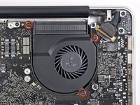
Use a spudger to pry the fan connector straight up off the logic board.
-
-
-
Remove the three T6 Torx screws securing the left fan to the logic board.
-
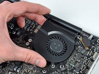
Lift the fan out of the upper case.
-
-
-
Use the flat end of a spudger to disconnect the left fan connector from the logic board.
-
-
-
Remove the three T6 Torx screws securing the left fan to the logic board.
-
Lift the left fan out of the upper case.
-
-
-
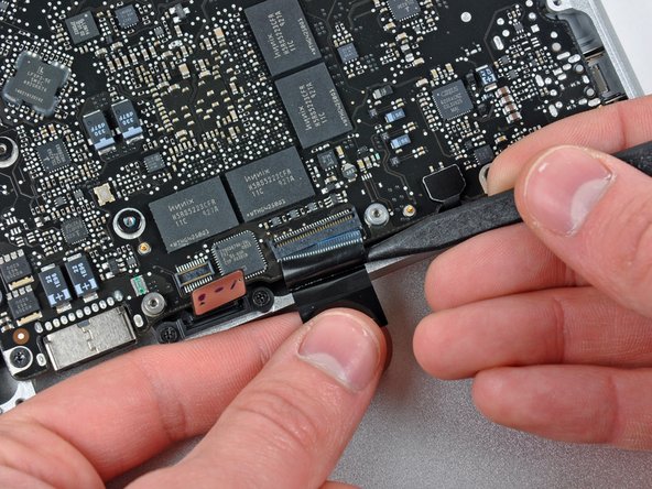
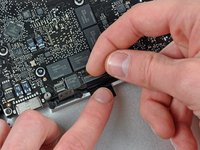
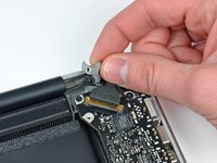
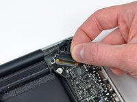
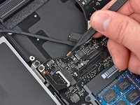
Hold the end of the cable retainer down with one finger while you use the tip of a spudger to slightly lift the other end and rotate it away from the camera cable connector.
-
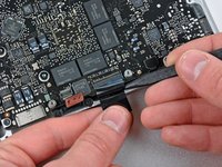
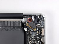
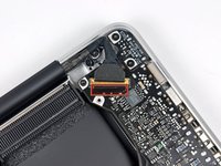
Disconnect the camera cable by pulling the male end straight away from its socket.
-
-
-
Disconnect the camera cable by pulling the male end straight away from its socket.
-
-
-
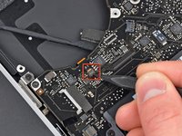
Use the flat end of a spudger to pry the optical drive cable connector up off the logic board.
-
-
-
Using the flat end of a spudger, pry the subwoofer connector straight up from the connector jack.
-
-
-
Use the flat end of a spudger to pry the hard drive/IR sensor cable connector up off the logic board.
-
-
-
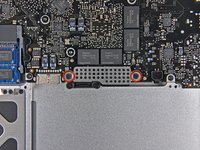
Remove the two 1.5 mm Phillips screws securing the cable cover to the logic board.
-
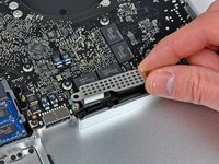
Lift the cable cover out of the upper case.
-
-
-
Use a spudger to pry the trackpad flex ribbon cable connector up off the logic board.
-
-
-
Use your fingernail to flip up the locking flap on the ZIF socket for the keyboard ribbon cable. The locking flap is located at the opposite side of the socket compared to the keyboard ribbon cable. Hook your fingernail under it and carefully lift it up vertically.
-
Use the tip of a spudger to slide the keyboard ribbon cable out of its socket.
-
-
-
Use a spudger to pry the battery indicator ribbon cable connector up off the logic board.
-
-
-
Remove the single 7 mm Phillips screw securing the display data cable retainer to the upper case.
-
Remove the display data cable retainer from the upper case.
-
-
-
Grab the plastic pull tab secured to the display data cable lock and rotate it toward the DC-in side of the computer.
-
-
-
Using the tip of a spudger, flip up the keyboard backlight ribbon cable retaining flap.
-
Pull the keyboard backlight ribbon cable straight out of its socket.
-
-
-
Remove the following screws:
-
Seven 3.3 mm T6 Torx screws securing the logic board to the upper case.
-
Two 8 mm T6 Torx screws securing the DC-In board to the upper case.
-
-
-
Carefully lift the logic board assembly from the left side and work it out of the upper case, minding the port side that may get caught during removal.
-
-
-
Lift the logic board enough to gain clearance and use a spudger to pry the microphone up off the upper case.
-
Slide the logic board away from the port openings and lift the assembly out of the upper case.
-
-
-
Slide the logic board away from the port openings and lift the assembly out of the upper case.
-


To reassemble your device, follow these instructions in reverse order.
To reassemble your device, follow these instructions in reverse order.
