Einleitung
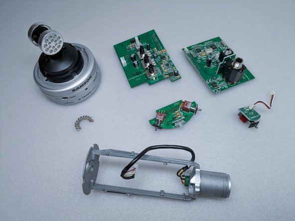
Zu Schritt 1 der AnleitungA complete disassembly of the Samson G-Track Pro microphone. This guide is intended to provide tips and techniques for the disassembly of the device, especially in areas that can be tricky without prior experience. While not a repair guide, reading the instructions in reverse can help with reassembly.
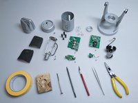
Was du brauchst


-
-
Angle the stand for better access to the bottom and unscrew the nut.
-
-
-
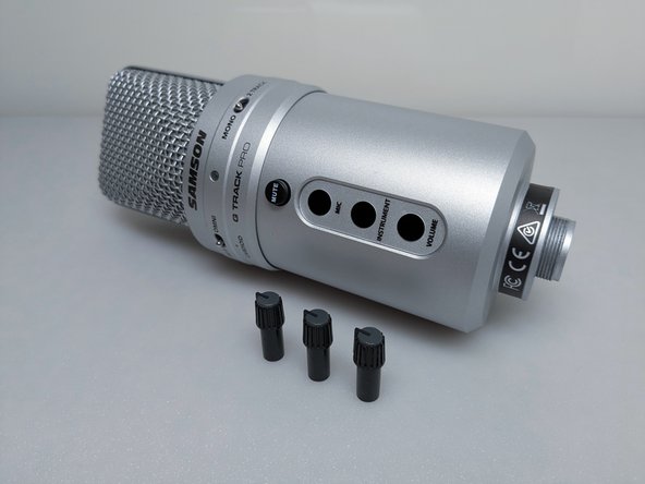
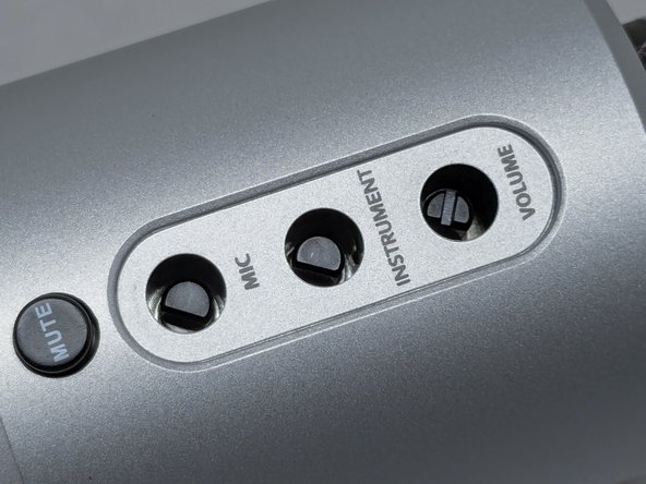
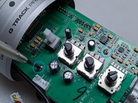
Pry at the bottom lip of each knob to lift them from their potentiometers. A spudger works best to prevent scratching, but a small flathead screwdriver can be used as well.
-
Once lifted, the knobs will be loose enough to pull off by hand.
-
The position of each knob does not matter, as they can only fit in one orientation.
-
-
-
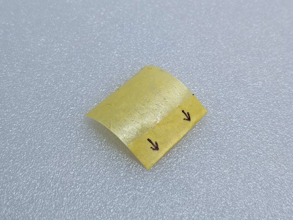
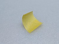
Cut a piece of tape 1.5in/4cm long and fold one end up by roughly 0.25in/6mm so that it sticks to itself.
-
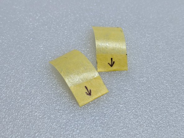
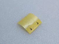
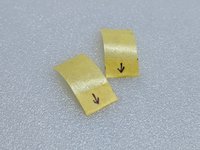
Cut the folded tape in half.
-
-
-
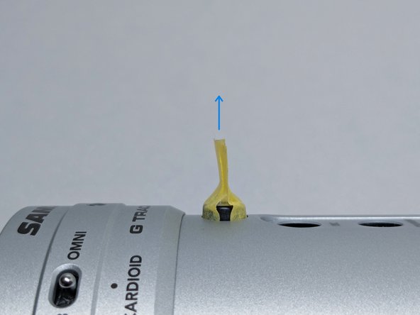
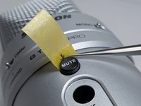
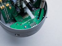
Insert the tape into the space between the body and the button, sticky side facing the button.
-
After inserting both pieces of tape, press on the area making contact with the button so that they adhere better.
-
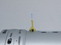
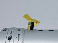
Stick the two pieces of tape together and pull directly upward. The button should come loose.
-
-
-
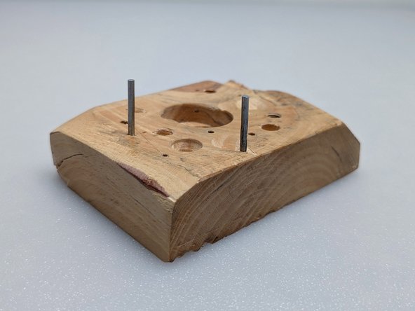
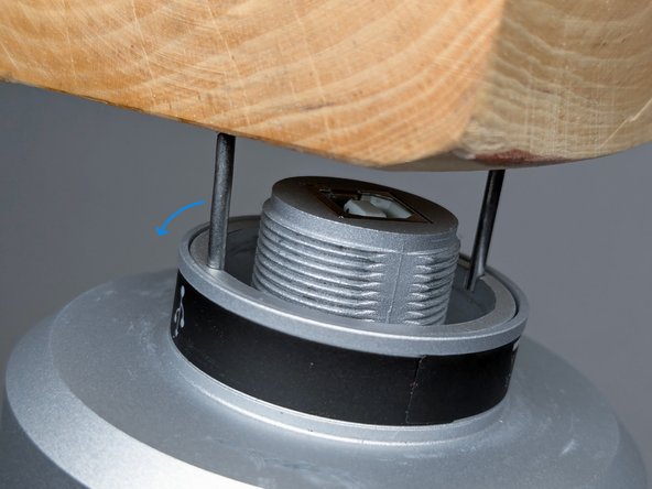
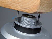
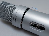
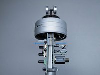
At the bottom of the microphone is a large nut that holds the body together. There are two recessed spots that can be used to loosen/tighten the nut.
-
A simple wrench can be made from a scrap piece of wood and two small nails. Drill two holes 32mm apart in the wood with a bit smaller than the nails. Tap the nails in, and if possible, cut and sand the tips so that they are flat and of the same height (prevents slipping).
-
If the nails do not fit in the recesses, they can be bent until they do.
-
If the nails flex too much and slip out while tightening, shortening the nails will make them stiffer.
-
-
-
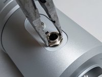
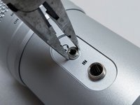
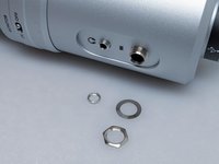
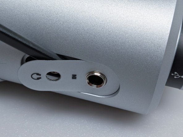
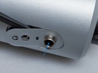
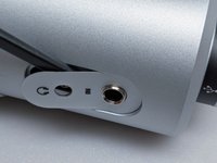
If the nuts that hold the jacks in place are too tight, they can be loosened with pliers. Otherwise, unscrew them by hand to prevent damage.
-
The washer on the 1/4" jack may be stubborn. "Unscrewing" it can help lift it enough to be pulled off.
-
-
-
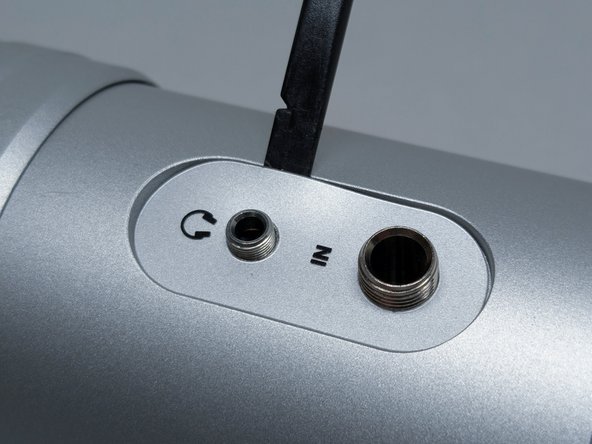
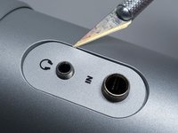
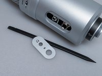
The part surrounding the jacks is a thick sticker. The tip of a hobby knife is the easiest way to lift the sticker. However, it is very likely to cause small scratches in the surrounding area. A small piece of tape beneath the blade can help protect the paint somewhat.
-
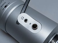
Once there is enough room, insert a plastic tool like a spudger or guitar pick to prevent further damage.
-
Gently pry the sticker so that the 3.5mm jack end can be lifted.
-
-
-
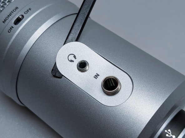
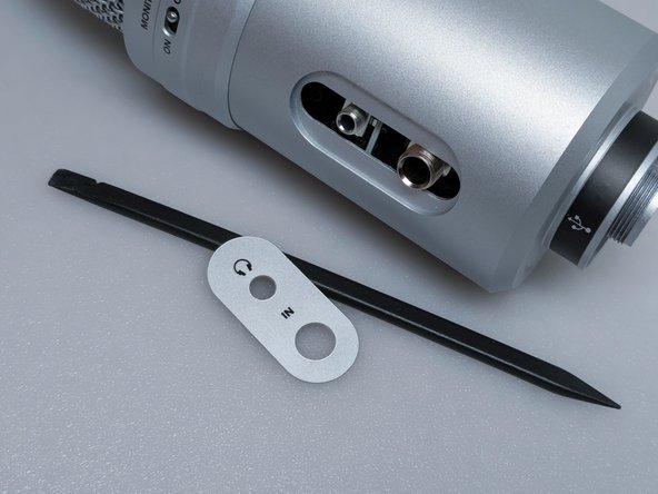
The 1/4" jack can be pushed into the body so that it is out of the way of the sticker. This makes the sticker much easier to remove without creasing.
-
-
-
-
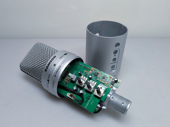
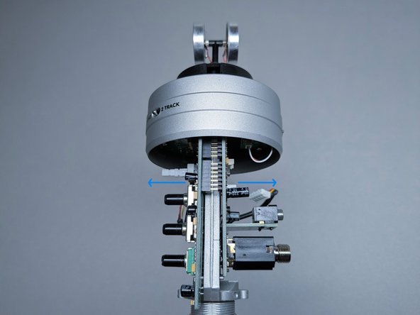
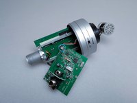
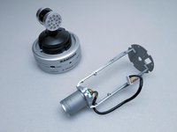
Slide the body directly downward until there is a gap between it and the head of the microphone.
-
Eventually, the body will make contact with the 3.5mm jack. Gently angle the body back and fourth so that it clears the jacks and the rest of the internals continue to slide the body downward.
-
-
-
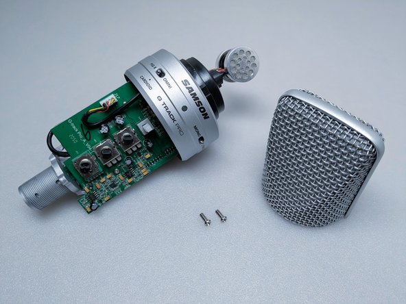
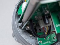
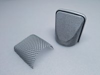
The head basket is attached with two screws at the base of the "band" where the mesh meets. Remove them with a #1 philips screwdriver and the head basket can be gently pulled off.
-
-
-
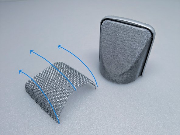
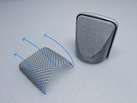
The thick mesh can be removed by grabbing the bottom edge and "flipping" it upward, as seen in the image.
-
The fine mesh seems to be attached permanantly and it it is not recommended to try removing it. Most dents can be reshaped in place.
-
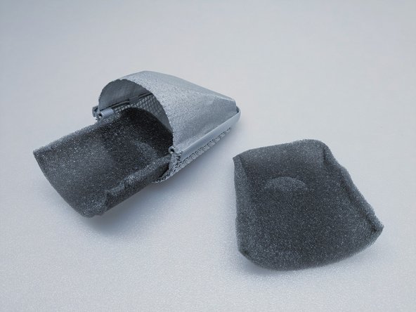
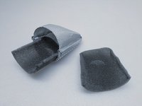
The foam inside can be lifted and removed easily.
-
-
-
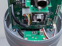
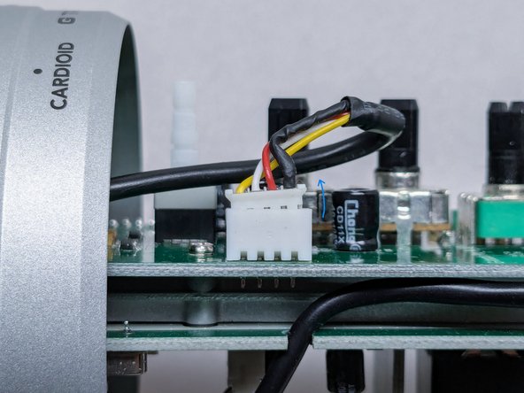
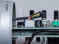
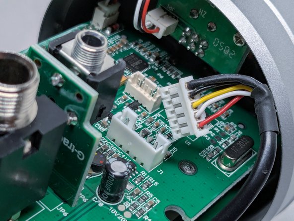
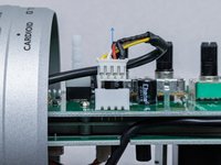
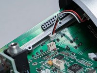
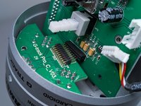
There are two large white connectors, one on each main board.
-
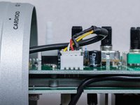
At the upper corners of the connectors, there are small ledges that are easily pulled on with fingernails.
-
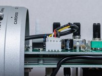
Gently pull on one side, then alternate with the other until the connector is loose.
-
-
-
Once the connectors are loose, they can be lifted upward with minimal force.
-
Repeat Step 12 and 13 for the large connector on the other board.
-
-
-
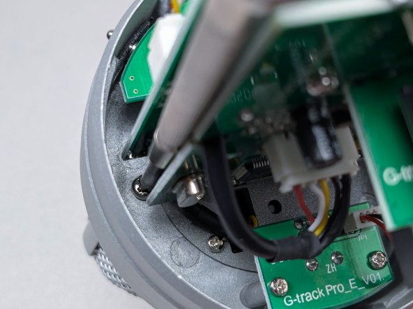
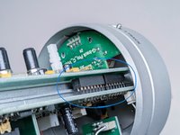
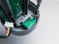
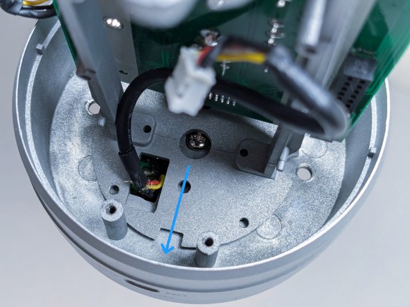
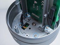
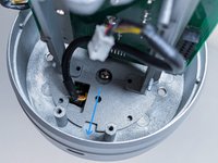
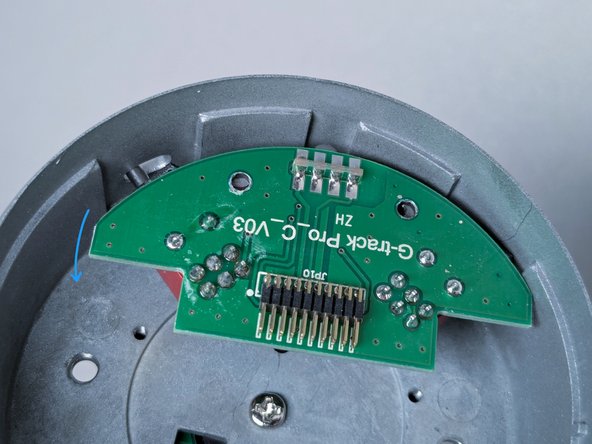
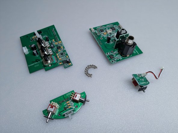
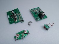
The only thing keeping the boards in place is an electrical connector between the volume board and the jack board.
-
Grip the boards by the edge and gently pull them apart from each other. Tilting the jack board back and fourth like the large white connectors (Step 12-13) will make removal more controlled and prevent it from coming apart suddenly.
-
Only the jack board can come off at this point. Leave the volume board alone once this step is complete.
-
-
-
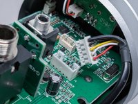
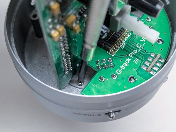
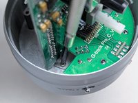
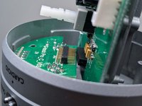
Remove the small white connector from the jack board in the same way as the large white connectors (Step 12-13).
-
Unscrew the monitor switch board and take it out. Unplugging the cable from this board is not necessary.
-
-
-
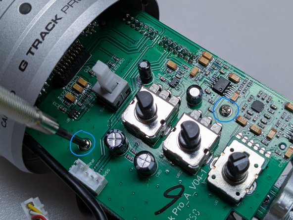
Move the board mount toward the back of the microphone, away from the circuit boards. Notice how the remaining screw is no longer centered in the hole.
-
-
-
Shifting the board mount provides enough room to separate the volume board from the switch board.
-
Disconnect the boards in the same way as before (Step 15). Then, remove the volume board from the microphone.
-
-
-
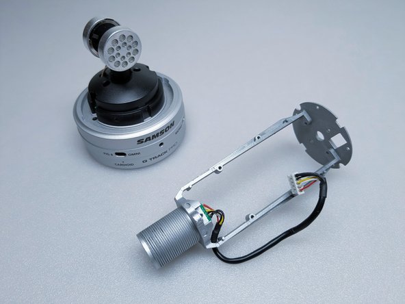
The board mount can be taken off, being careful not to snag the capsule cable or switch board.
-
The switch board can be removed afterward. The switches can get caught in the housing, so placing them in the "Omni" and "Mono" positions helps release it.
-
-
-
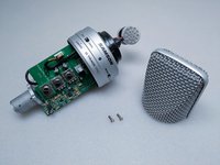
If not removed previously, now is the best time to take the head basket off. Take out the 2 large silver screws at either side of the central screw and gently lift the head basket.
-
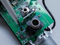
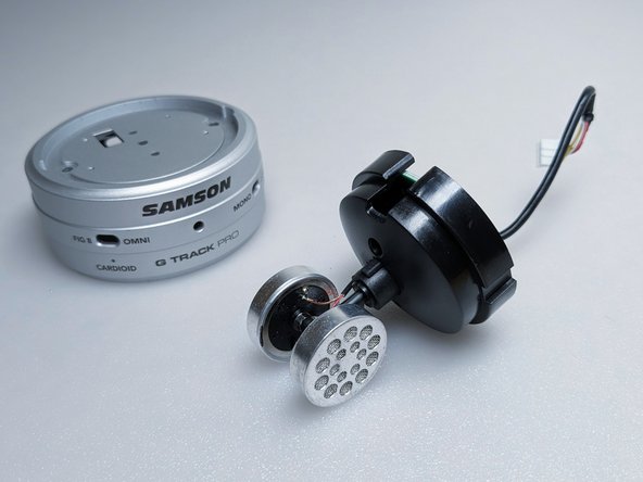
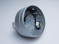
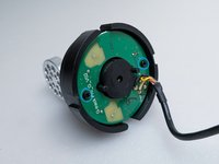
The capsule mount is attached to the housing with 1 large silver screw. Support the mount so that it does not fall off once the screw is completely out.
-
-
-
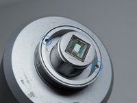
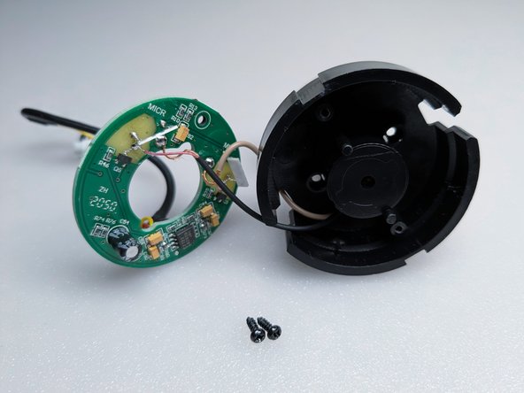
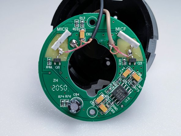
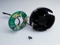
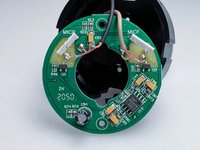
The capsule board is attached to the capsule mount with 2 small black screws.
-
-
-
Congrats! I hope your repair goes well. If you have suggestions, please leave them in the comments and the guide will be updated as needed.
-