Einleitung
This repair guide was authored by the iFixit staff and hasn’t been endorsed by Google. Learn more about our repair guides here.
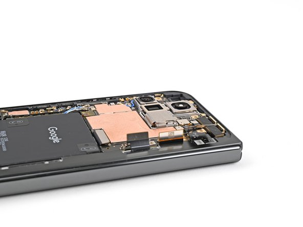
Use this guide to replace the inner screen assembly in your Google Pixel 9 Pro Fold.
Was du brauchst
-
-
Unplug all cables from your phone and completely power it down.
-
-
-
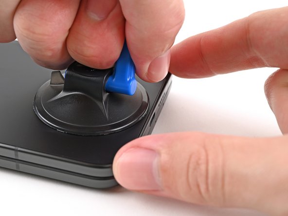
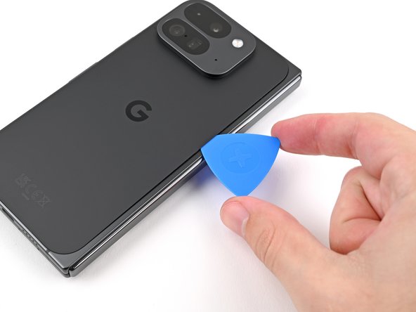
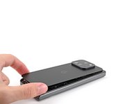
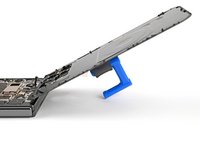
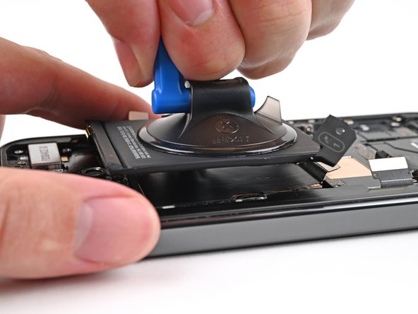
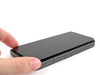
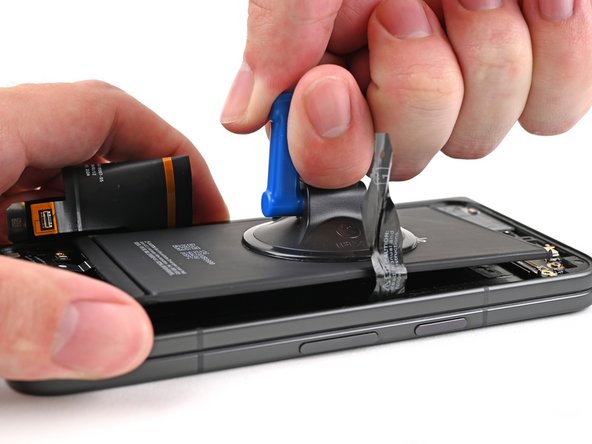
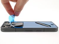
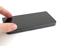
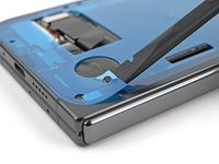
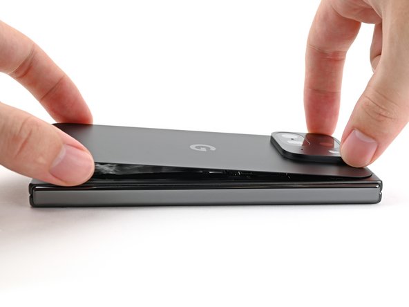
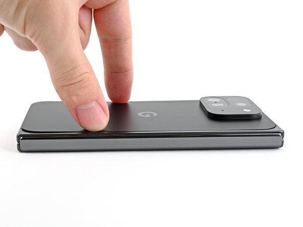
Apply a suction cup to the back cover, as close to the center of the bottom edge as possible.
-
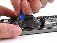
While securing the phone with one hand, pull up on the suction cup with strong, steady force to create a gap between the back cover and the frame.
-
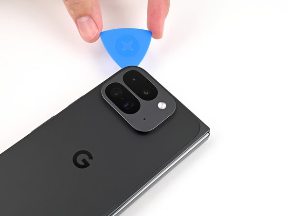
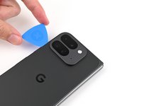
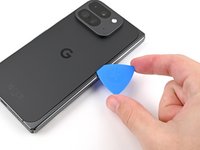
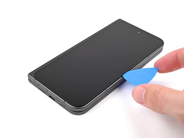
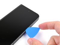
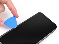
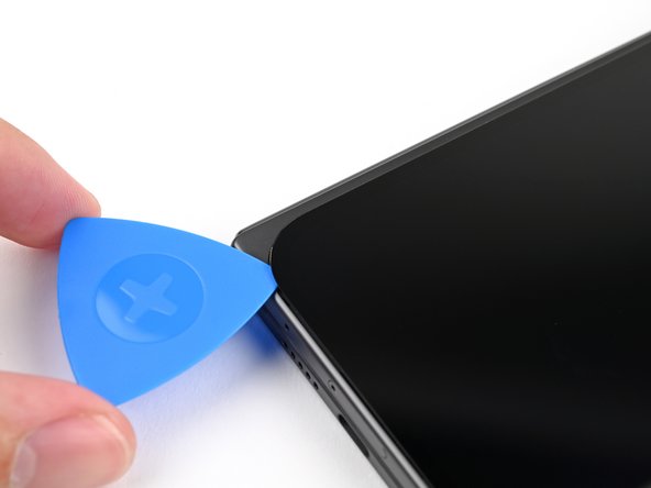
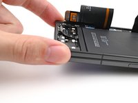
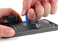
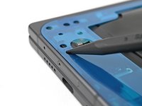
Insert an opening pick into the gap.
-
-
-
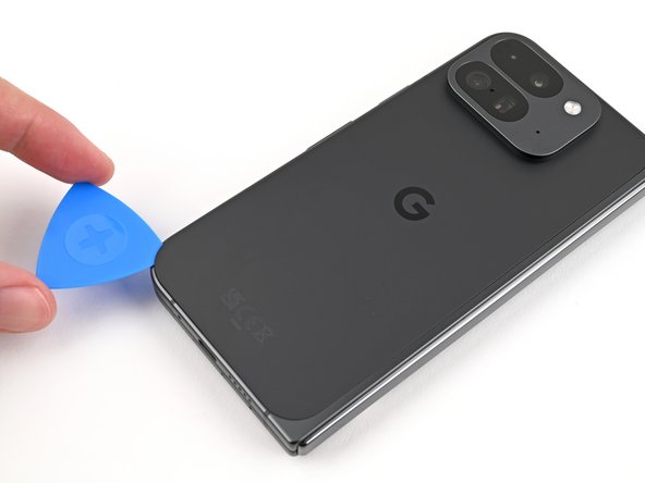
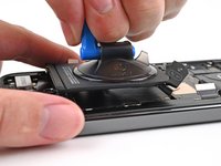
Remove the suction handle from the back cover.
-
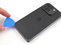
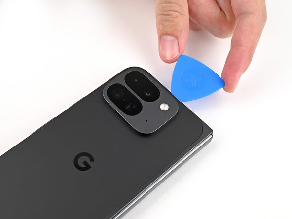
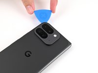
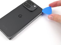
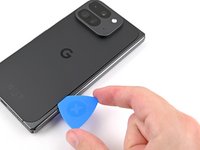
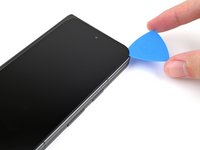
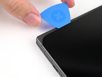
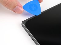
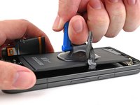
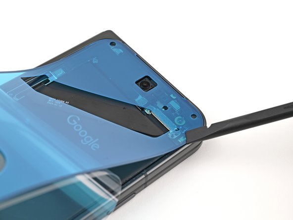
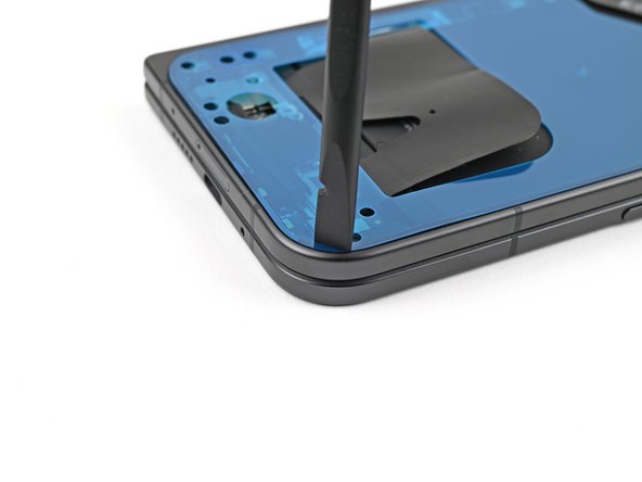
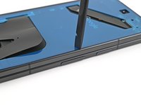
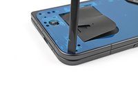
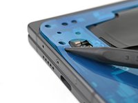
Slide the opening pick around the bottom left corner and up the left edge of the back cover to separate the adhesive.
-
-
-
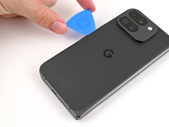
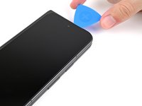
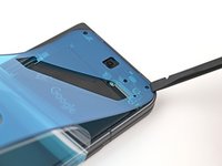
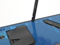
Continue sliding the pick around the top left corner and across the top edge of the back cover.
-
-
-
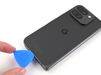
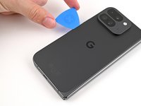
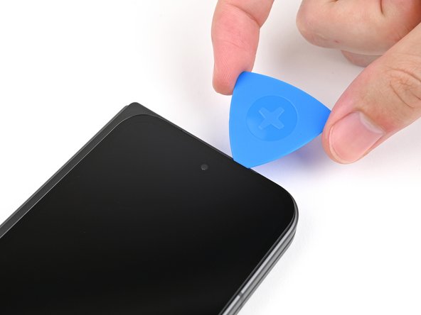
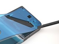
Slide your pick down the right edge and around the bottom right corner to separate the remaining adhesive.
-
-
-
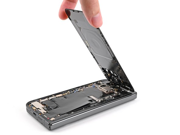
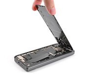
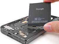
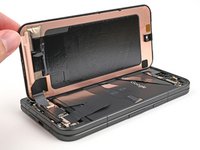
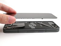
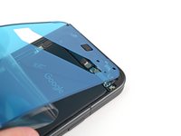
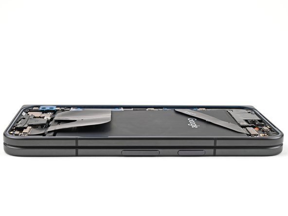
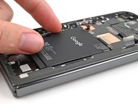
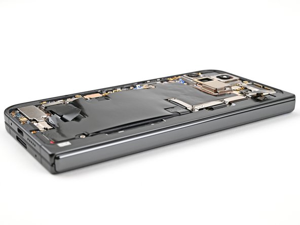
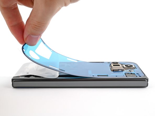
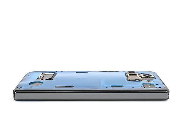
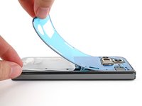
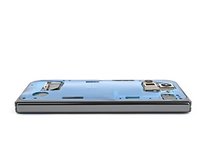
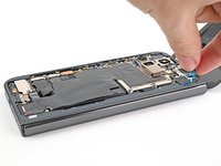
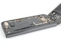
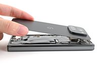
Lift the bottom edge of the back cover and swing it over the top edge of the phone.
-
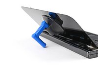
Prop up the back cover with your suction handle or a clean, sturdy object—making sure that the cable isn't strained.
-
-
In diesem Schritt verwendetes Werkzeug:FixMat$36.95
-
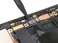
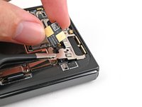
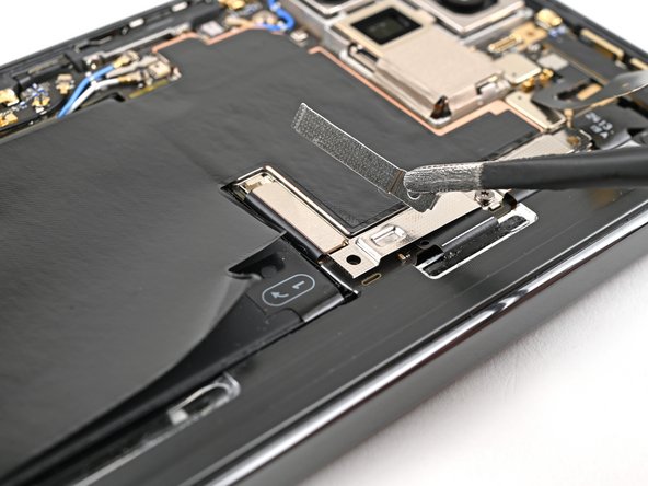
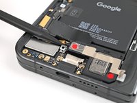
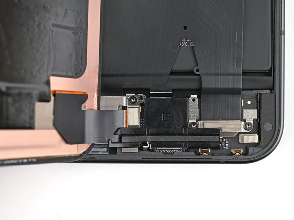
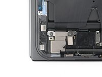
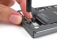
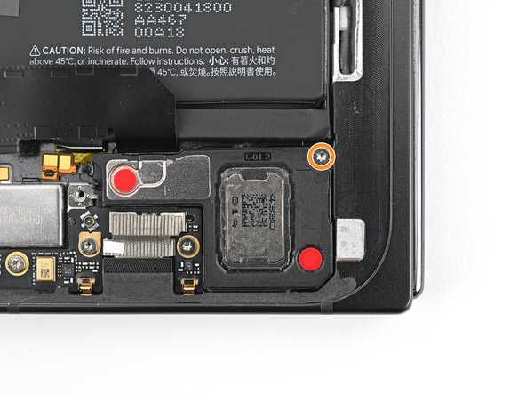
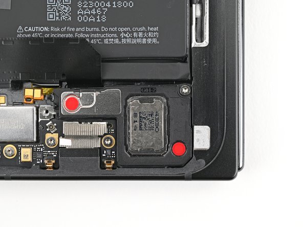
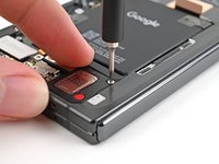
Use a Torx Plus 3IP driver to remove the 3.0 mm‑long screw securing the top bracket.
-
-
-
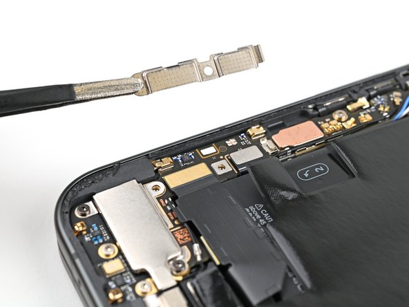
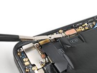
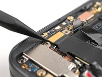
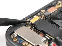
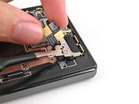
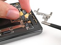
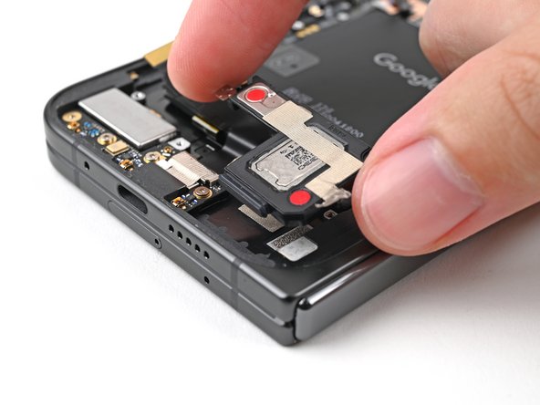
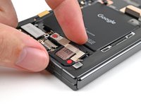
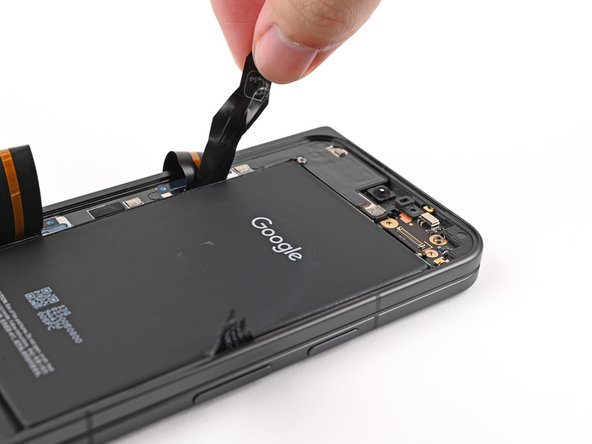
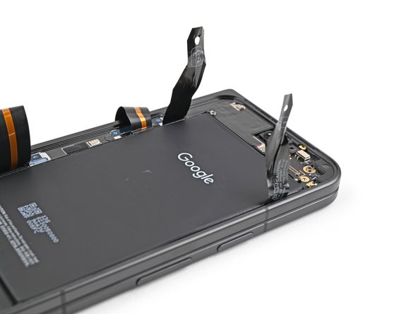
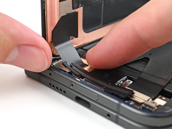
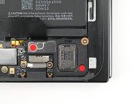
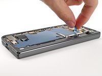
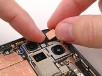
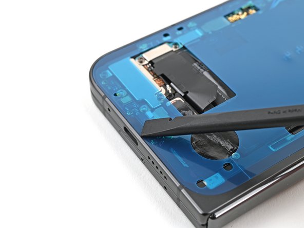
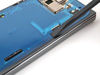
Use tweezers, or your fingers, to pull the top bracket towards the top of the phone to release it from its clip.
-
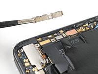
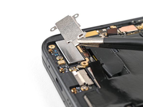
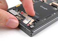
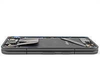
Remove the top bracket.
-
-
-
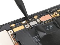
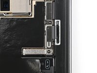
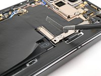
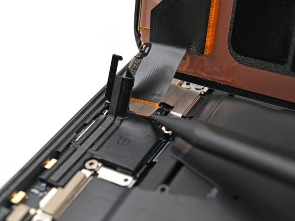
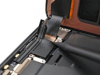
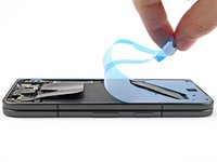
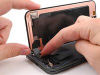
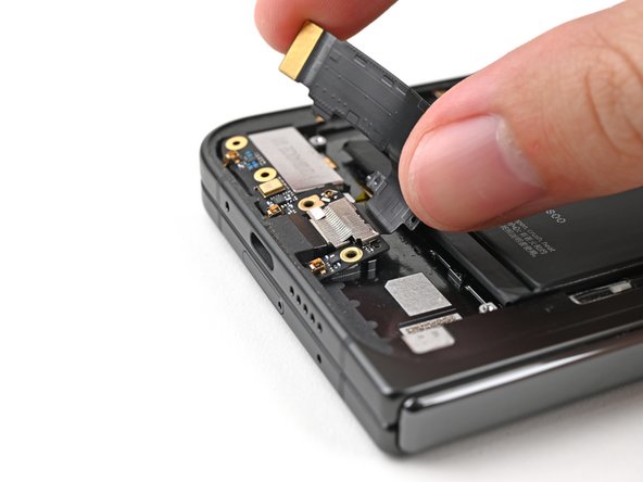
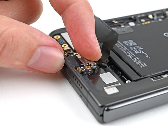
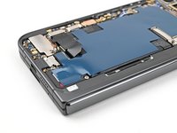
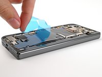
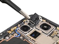
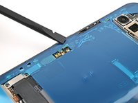
Insert the tip of your spudger under the bottom edge of the back cover cable press connector.
-
Pry up and disconnect the back cover cable.
-
-
-
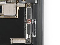
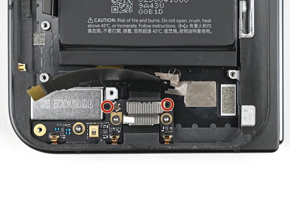
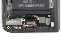
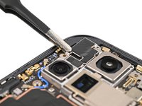
Use a Torx Plus 3IP driver to remove the two 3.0 mm‑long screws securing the base battery bracket.
-
-
-
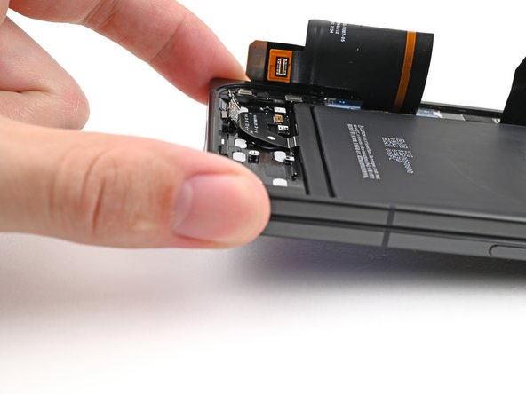
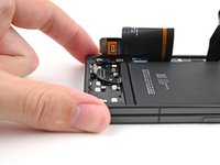
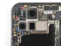
Use tweezers, or your fingers, to pull the base battery bracket toward the bottom of the phone to release it from its clip.
-
Remove the base battery bracket.
-
-
-
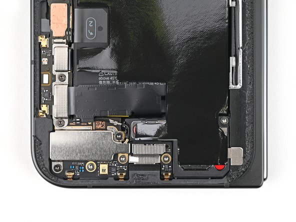
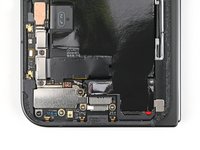
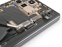
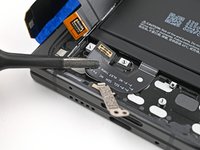
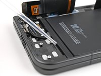
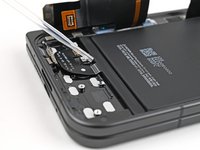
Insert the tip of your spudger under the bottom left corner of the base battery press connector, near the gold marker.
-
Pry up and disconnect the base battery.
-
-
-
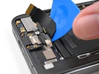
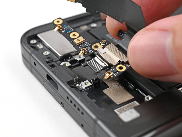
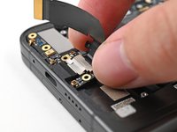
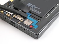
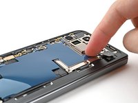
Use a spudger to pry up and disconnect the USB-C port board cable press connector.
-
-
-
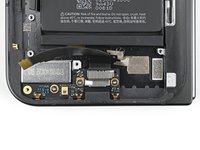
Use a Torx Plus 3IP driver to remove the two 3.0 mm‑long screws securing the vibrator bracket.
-
-
-
Use tweezers, or your fingers, to lift the vibrator bracket off the frame and remove it.
-
-
-
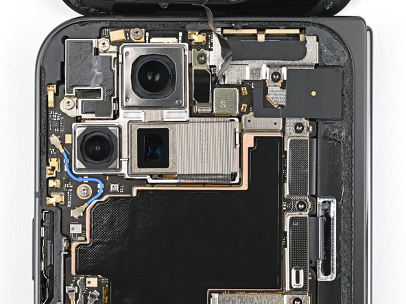
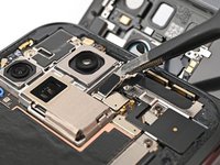
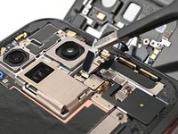
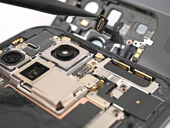
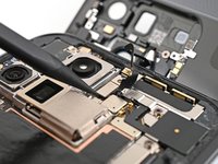
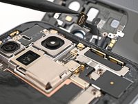
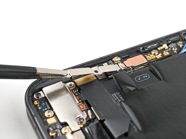
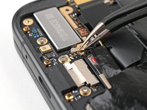
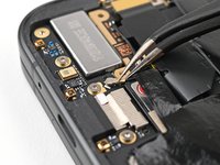
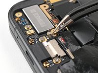
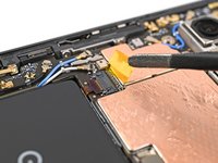
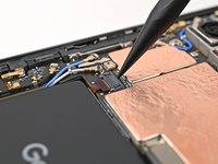
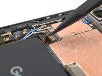
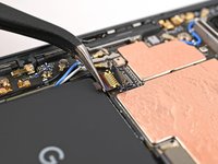
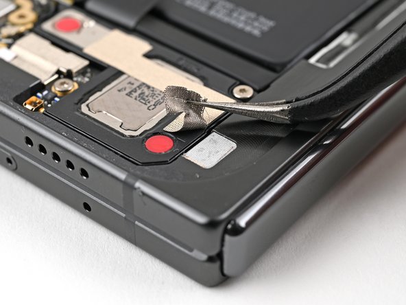
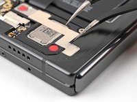
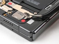
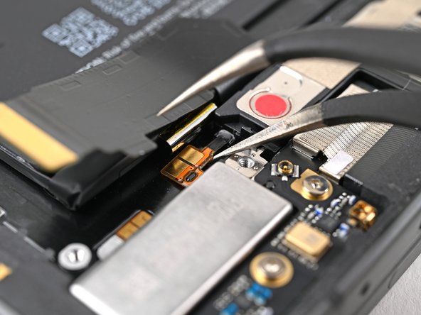
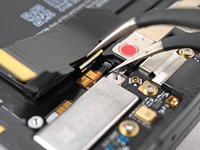
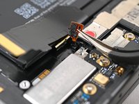
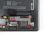
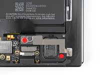
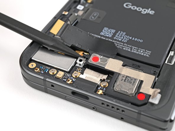
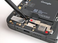
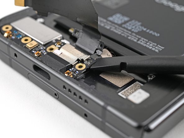
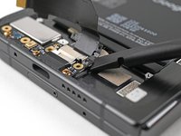
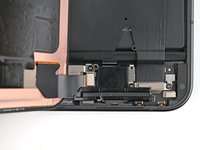
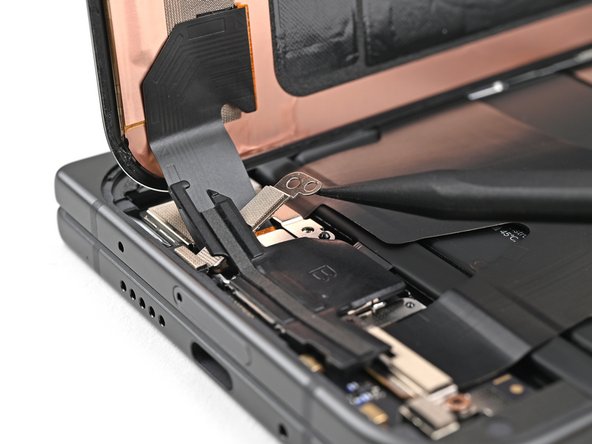
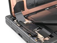
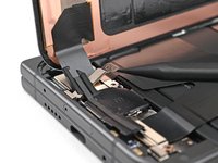
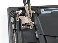
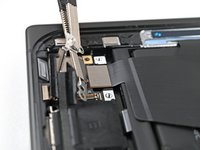
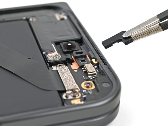
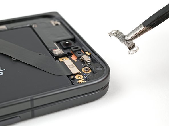
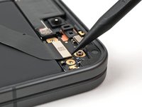
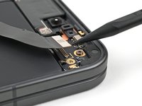
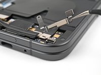
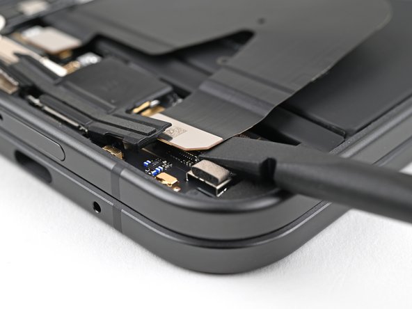
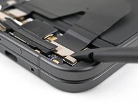
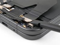
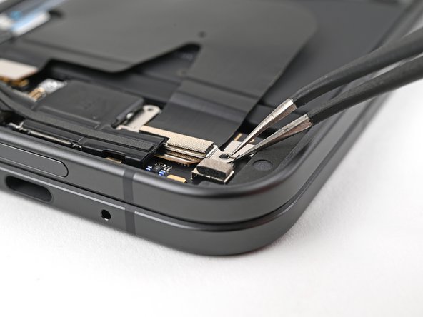
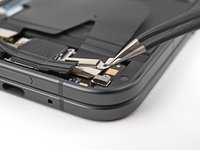
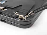
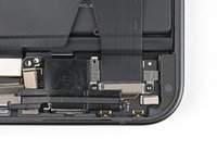
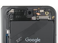
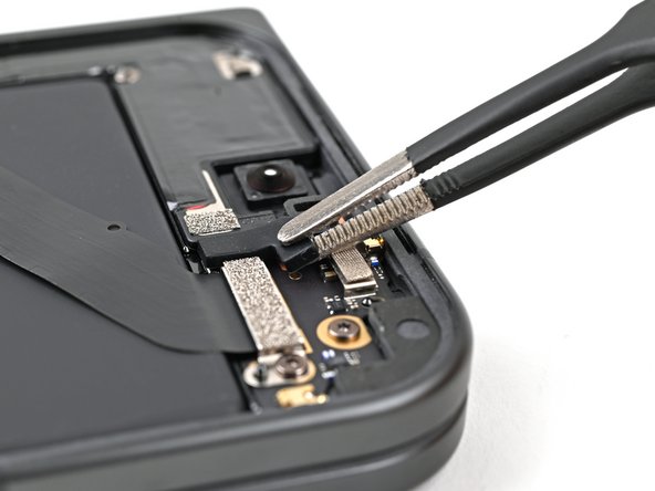
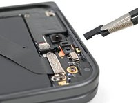
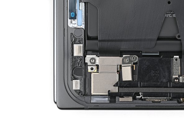
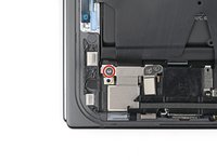
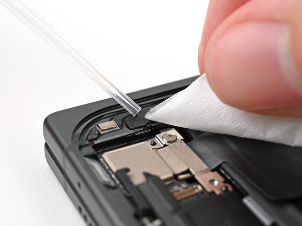
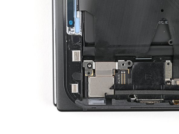
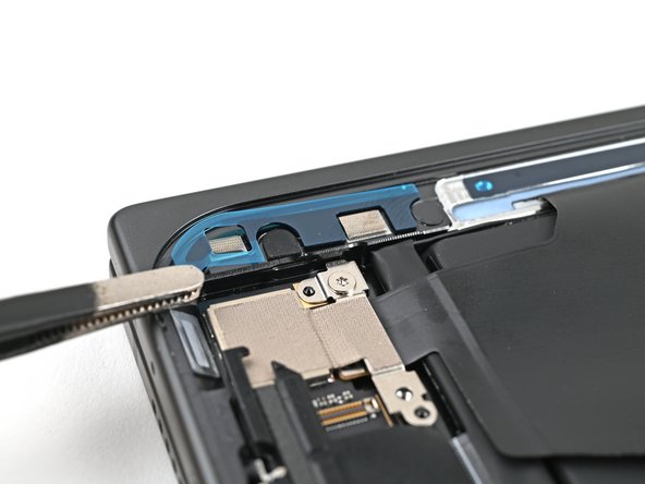
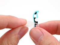
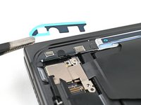
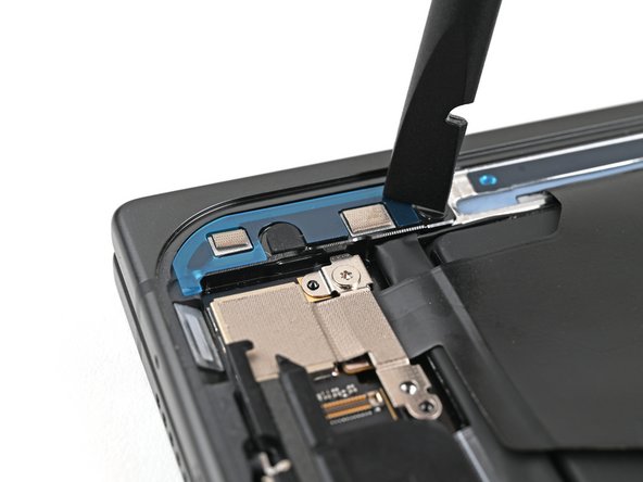
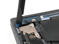
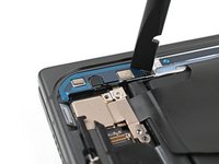
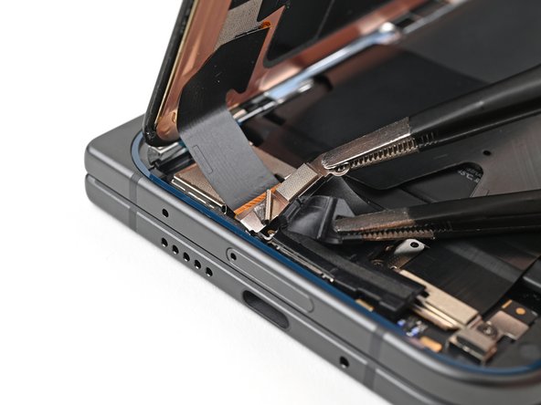
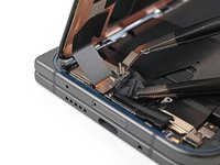
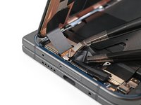
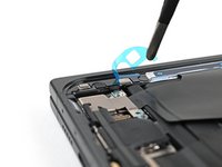
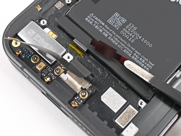
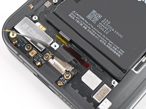
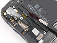
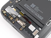
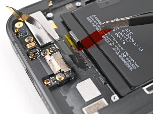
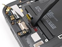
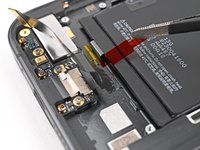
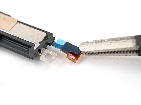
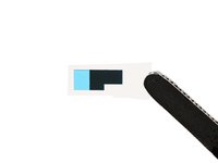
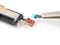
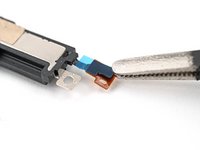
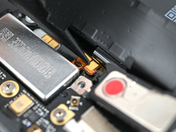
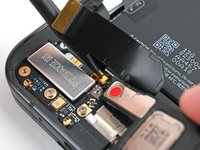
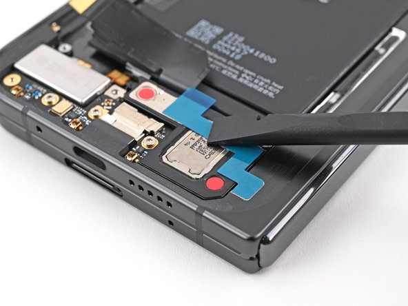
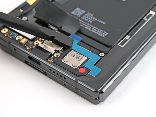
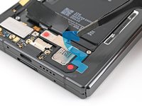
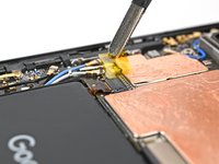
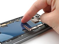
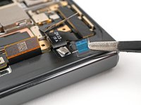
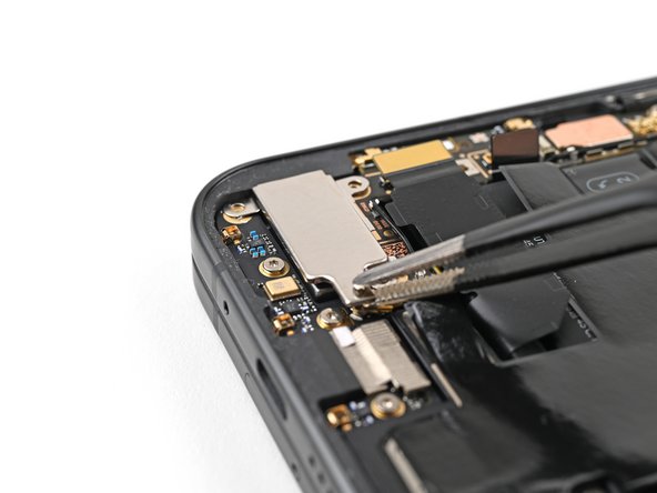
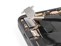
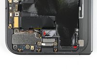
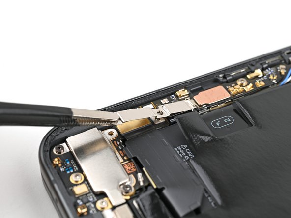
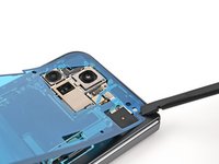
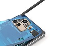
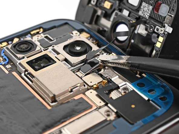
Slide one arm of a pair of angled tweezers under the metal neck of the black antenna cable's connector head on the USB‑C board.
-
Lift straight up to disconnect the cable.
-
-
-
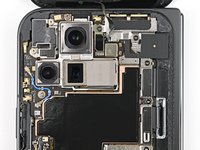
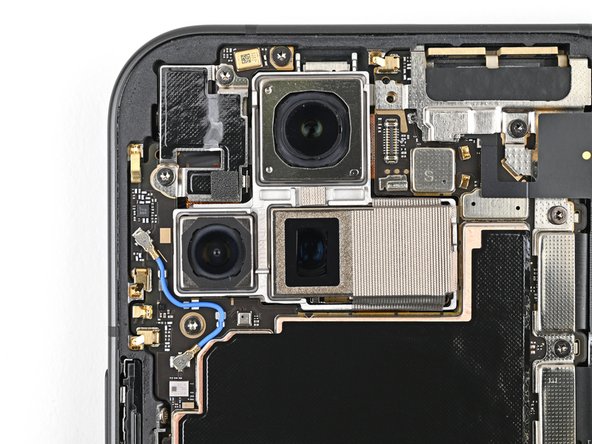
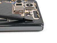
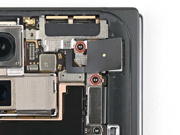
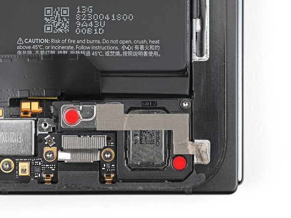
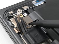
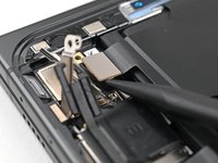
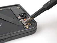
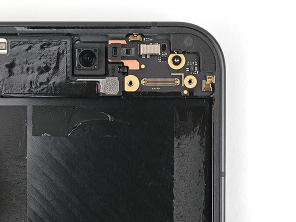
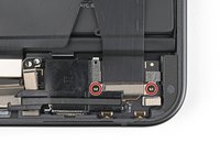
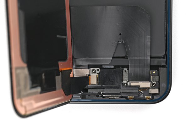
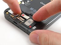
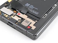
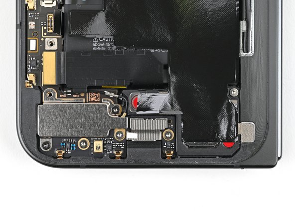
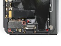
Use a Torx Plus 3IP driver to remove the two 2.6 mm‑long screws securing the inner front camera bracket.
-
-
-
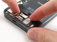
Use tweezers, or your fingers, to lift the inner front camera bracket up and toward the left edge of the phone to release its clips.
-
Remove the inner front camera bracket.
-
-
-
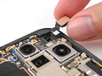
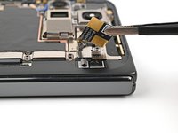
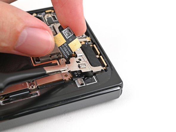
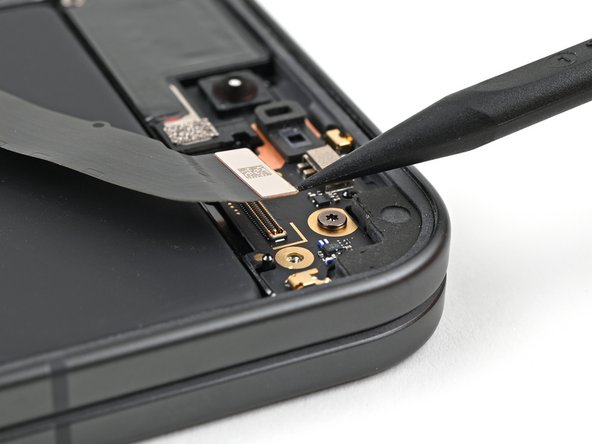
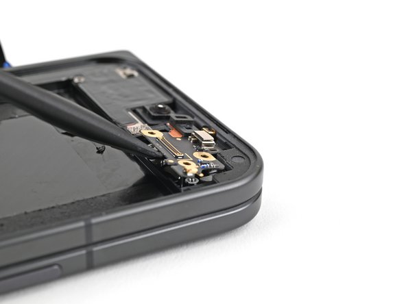
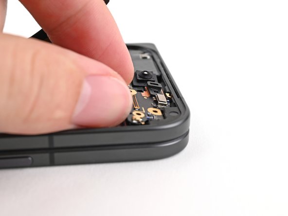
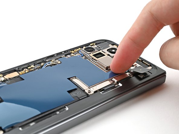
Use a spudger to pry up and disconnect the inner front camera press connector.
-
-
-
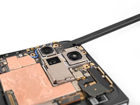
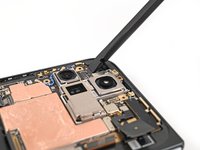
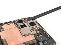
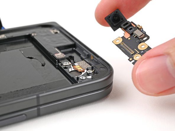
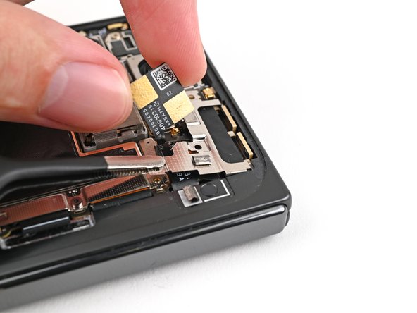
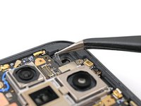
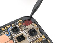
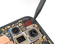
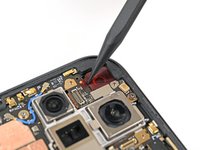
Use the point of a spudger to pry up the inner front camera and separate the adhesive securing it to the frame.
-
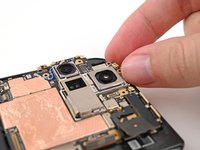
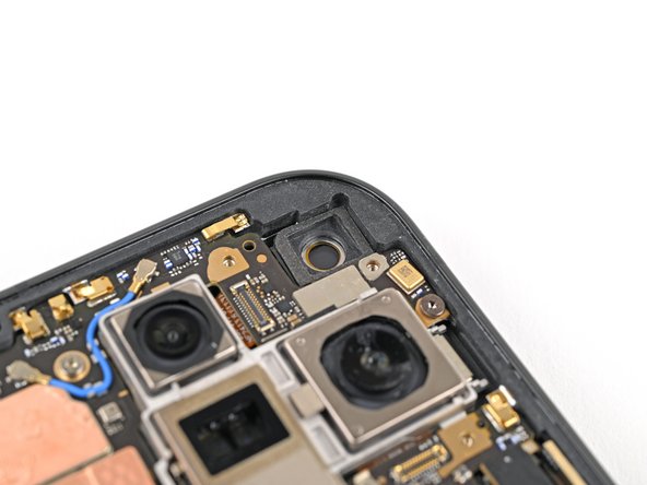
Remove the inner front camera.
-
-
-
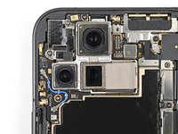
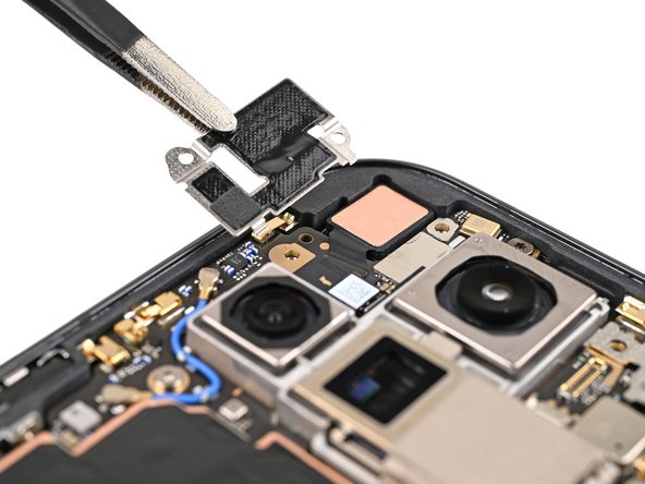
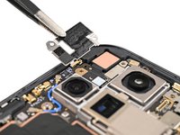
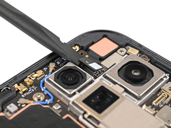
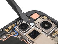
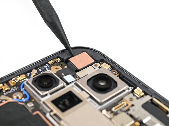
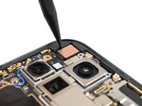
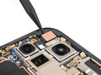
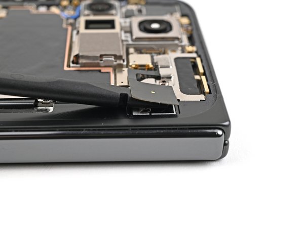
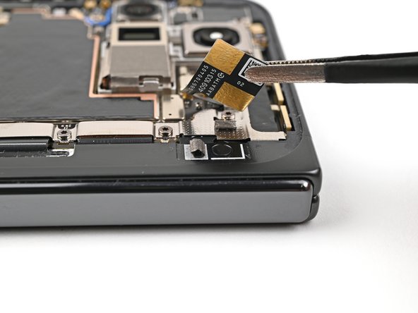
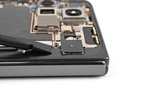
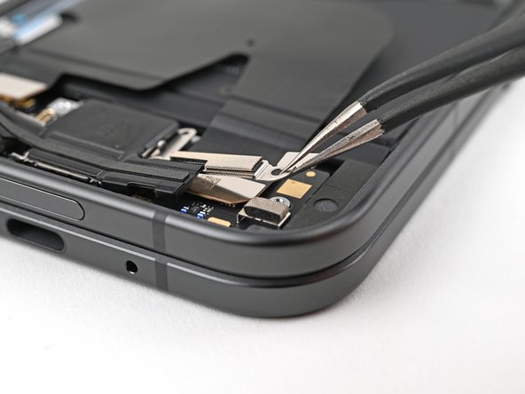
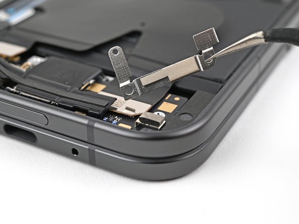
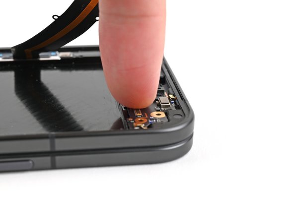
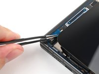
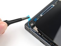
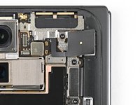
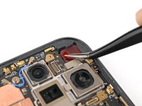
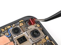
Slide the flat end of a spudger under the ultra wideband antenna to separate the adhesive foam securing it to the frame.
-
Use tweezers, or your fingers, to lift the antenna off the frame to separate any remaining adhesive.
-
-
-
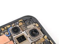
Use a Torx Plus 3IP driver to remove the two 3.0 mm‑long screws securing the ultra wideband bracket.
-
-
-
While holding the ultra wideband antenna out of the way, pull the bracket toward the bottom of the phone to release its clips.
-
Remove the ultra wideband bracket.
-
-
-
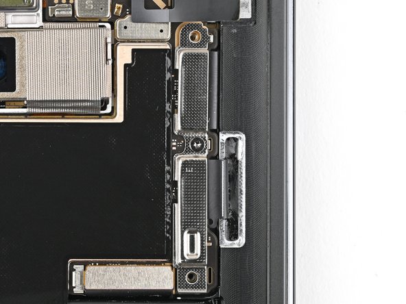
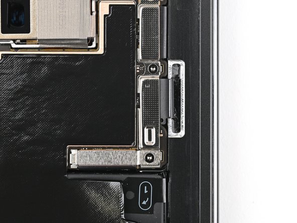
Use a Torx Plus 3IP driver to remove the 3.0 mm‑long screw securing the interconnect cable bracket.
-
-
-
Use tweezers, or your fingers, to pull the bracket toward the right edge of the phone to release its clip.
-
Remove the bottom interconnect cable bracket.
-
-
-
Use a Torx Plus 3IP driver to remove the 3.0 mm‑long screw securing the inner display cable bracket.
-
-
-
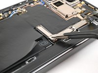
Use tweezers, or your fingers, to pull the inner display cable bracket towards the left edge of the phone to release it from its clip.
-
Remove the inner display cable bracket.
-
-
-
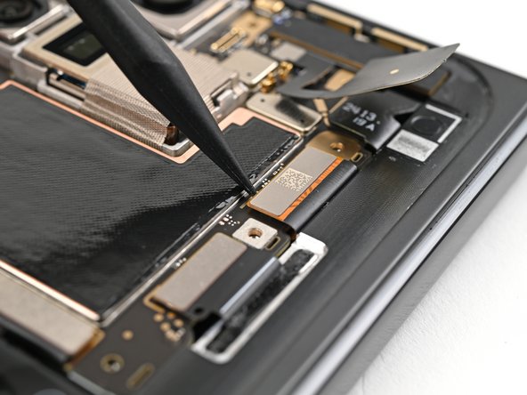
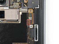
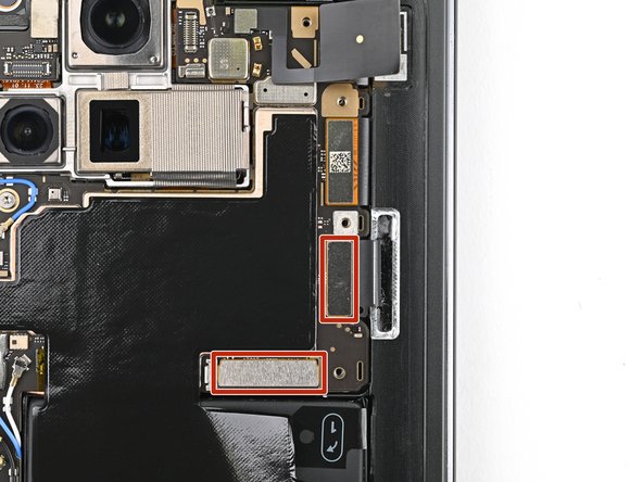
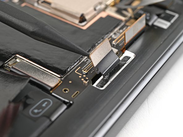
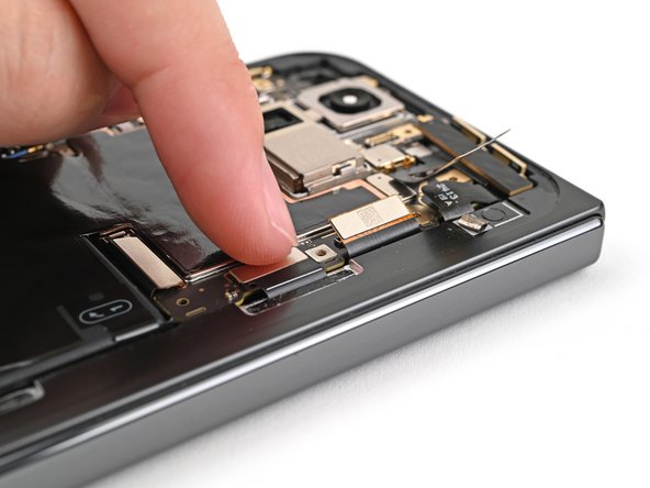
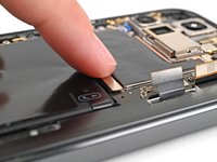
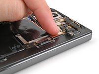
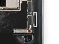
Insert the point of a spudger under the bottom left corner of the inner display press connector, next to the gold marker on the logic board.
-
Pry up and disconnect the inner display cable.
-
-
-
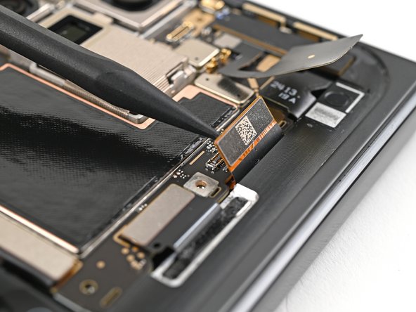
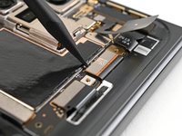
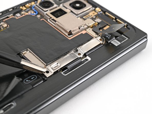
Repeat the previous step to disconnect the top and bottom interconnect cable press connectors, making sure to only pry next to the gold markers.
-
-
-
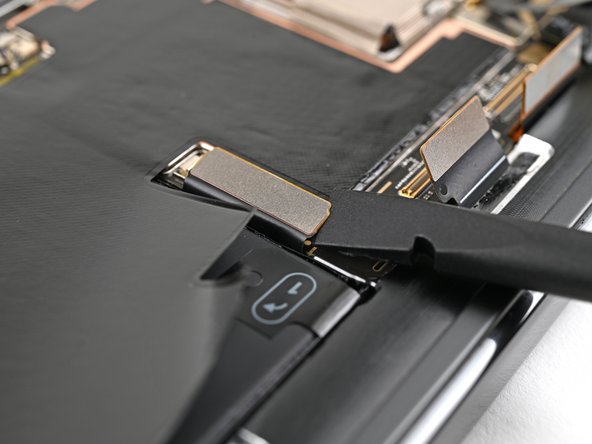
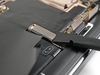
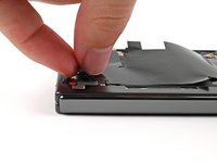
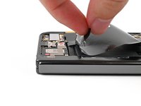
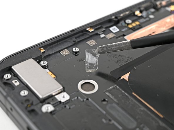
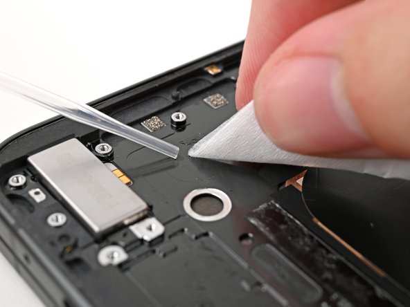
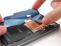
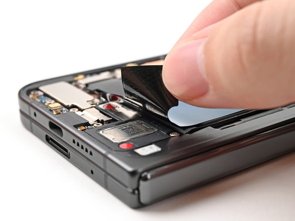
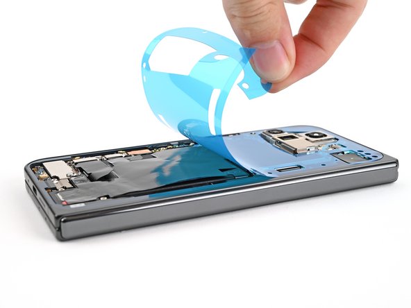
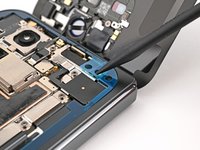
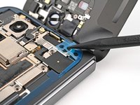
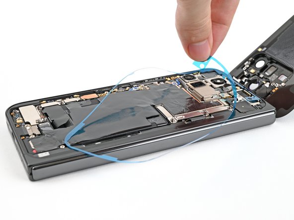
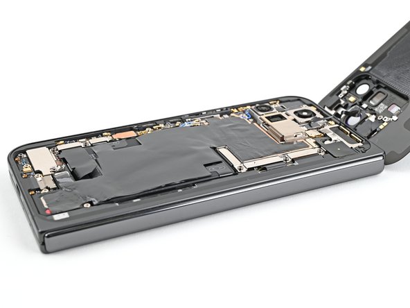
Peel the graphite sheet off the bottom speaker to separate the adhesive securing it.
-
-
-
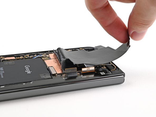
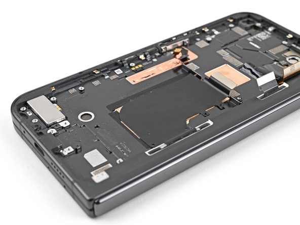
Continue peeling the graphite sheet off the logic board to separate the remaining adhesive.
-
-
-
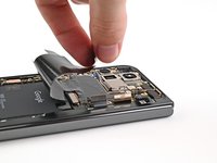
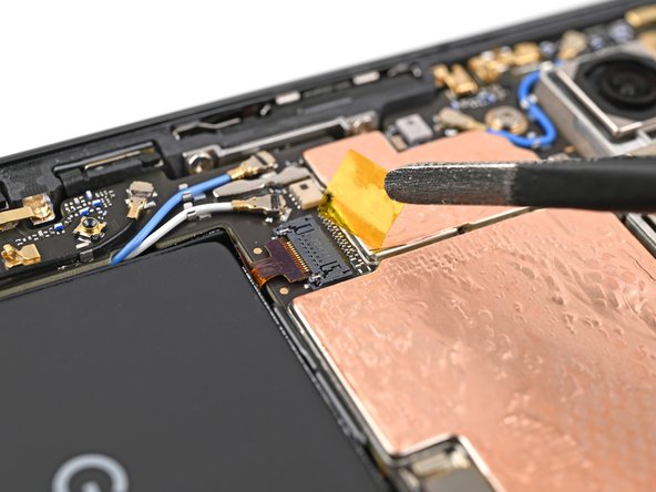
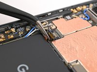
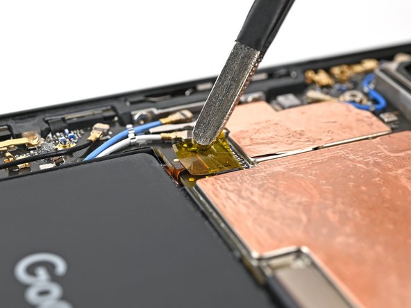
Use tweezers, or your fingers, to peel off the yellow tape on the side button cable ZIF connector.
-
-
-
Use the point of a spudger, or your fingernail, to lift the locking tab on the side button cable ZIF connector.
-
-
-
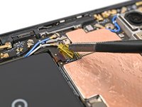
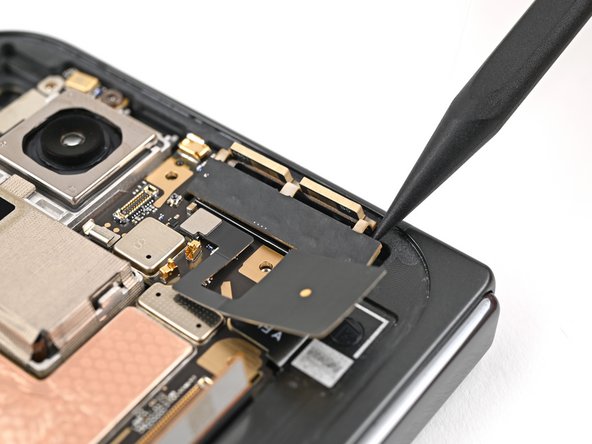
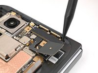
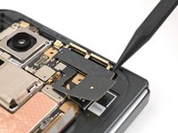
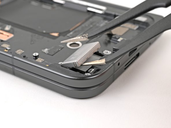
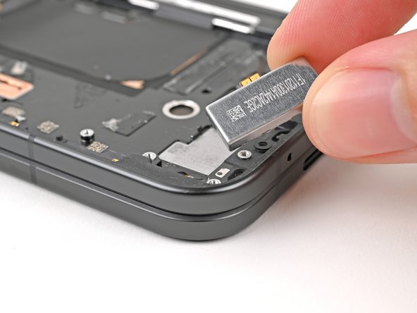
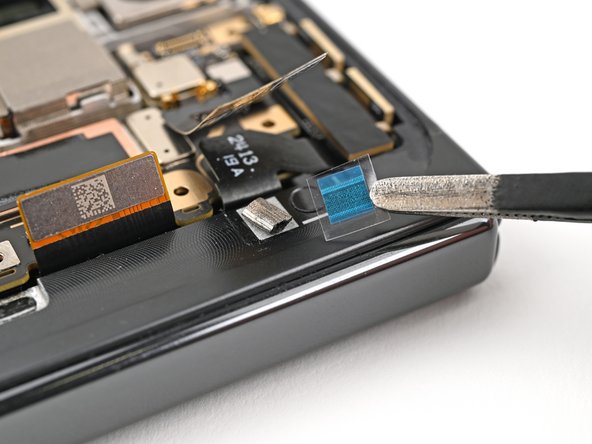
Use the tip of a spudger to pry up the 5G mmWave antenna from the frame and separate it from the thermal pad.
-
-
-
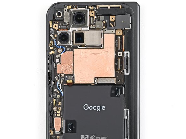
Use a Torx Plus 3IP driver to remove the three screws securing the logic board:
-
One 2.2 mm‑long screw
-
Two 2.6 mm‑long screws
-
-
-
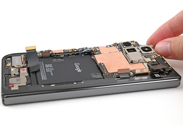
Insert the flat end of a spudger under the top left corner of the logic board, next to the inner front camera cutout.
-
Pry up the logic board enough so you can grip the top edge with your fingers.
-
-
-
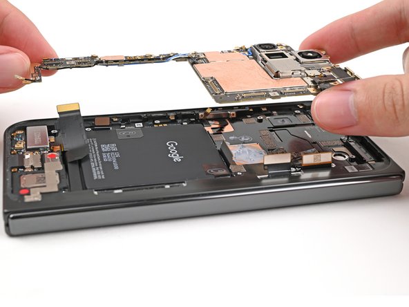
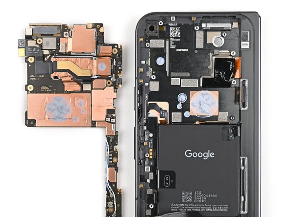
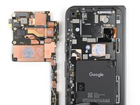
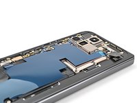
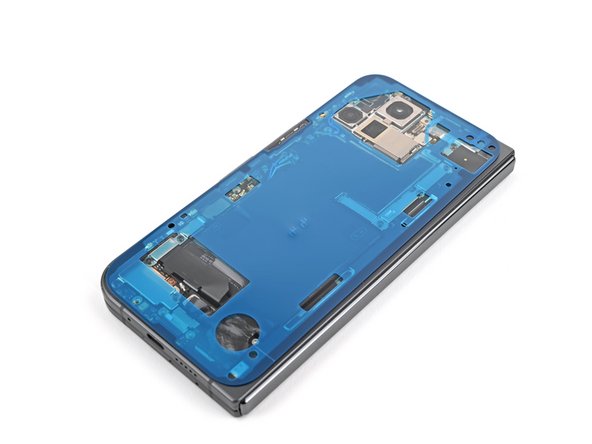
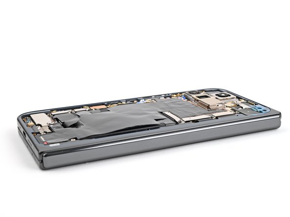
Lift the top of the logic board out of the frame and remove it.
-
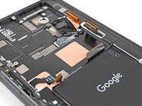
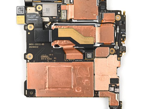
Lay down the logic board upside down on a clean surface.
-
-
-
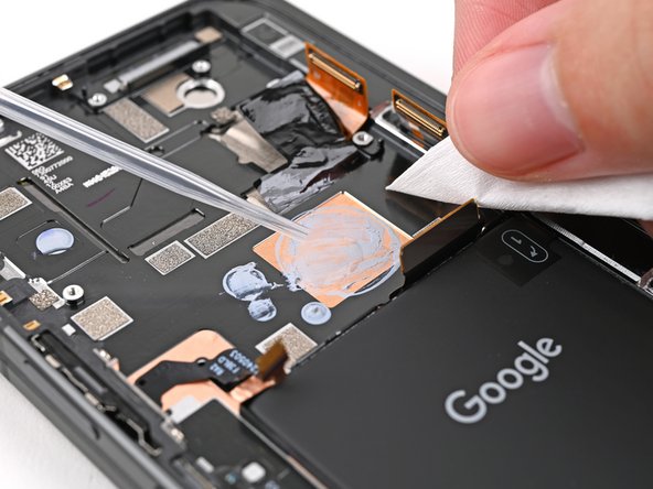
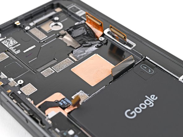
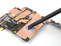
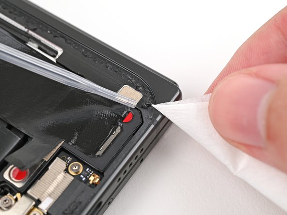
Use the flat end of a spudger to scrape away large pieces of old thermal paste from the frame.
-
Apply a few drops of highly-concentrated isopropyl alcohol (over 90%) to any remaining thermal paste residue.
-
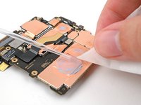
Wipe away the residue using a coffee filter or lint-free cloth.
-
-
-
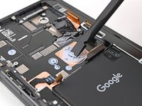
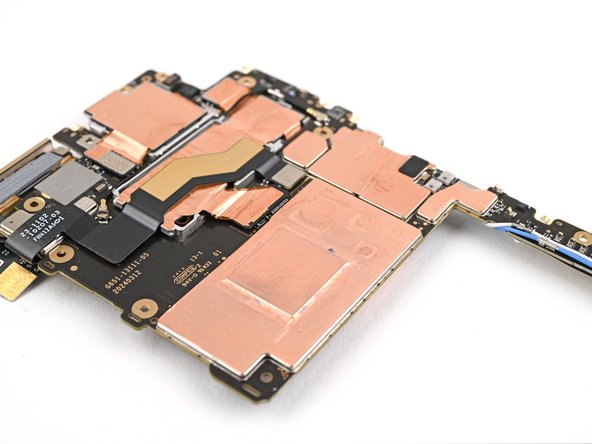
Repeat the thermal paste cleaning procedure for the bottom of the logic board.
-
-
-
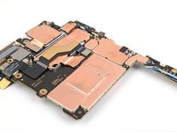
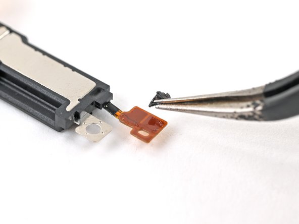
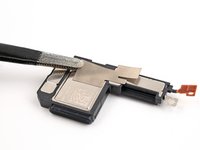
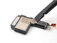
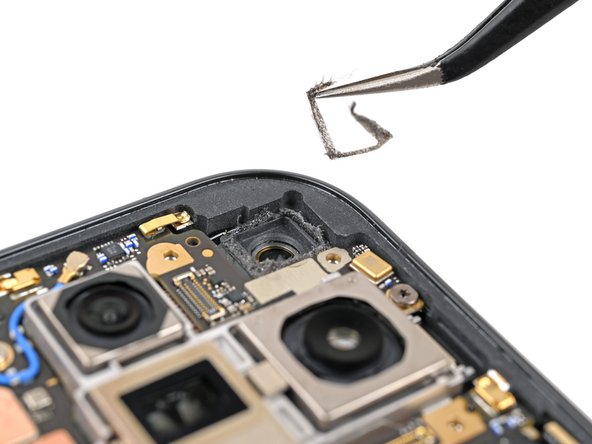
Use tweezers, or your fingers, to peel the section of conductive fabric connecting the loudspeaker to the frame.
-
-
-
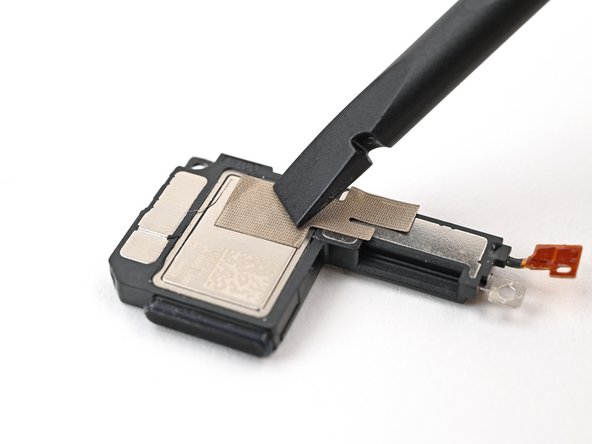
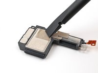
Slide one arm of a pair of angled tweezers under the contact pad connected to the loudspeaker.
-
Lift the contact pad to separate the adhesive securing it to the frame.
-
-
-
Use a Torx Plus 3IP driver to remove the 2.6 mm‑long screw securing the loudspeaker.
-
-
-
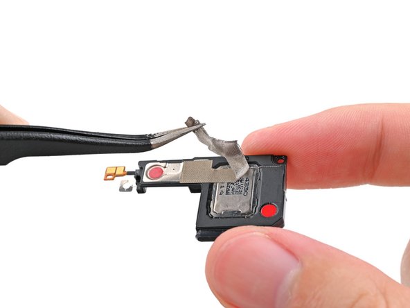
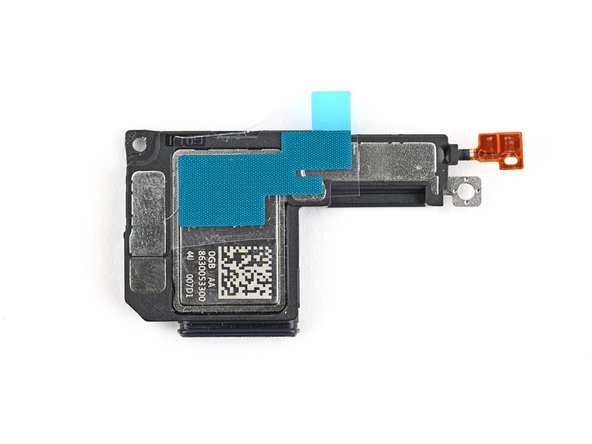
Use the tip of a spudger to pry up the left edge of the loudspeaker to separate the adhesive securing it to the frame.
-
-
-
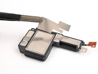
Use your fingers to lift the top edge of the loudspeaker and pull it out of its recess in the frame.
-
Remove the loudspeaker.
-
-
-
Slide the tip of an opening pick under the USB-C port board cable to separate the adhesive securing it to the frame.
-
-
-
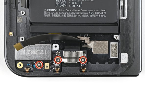
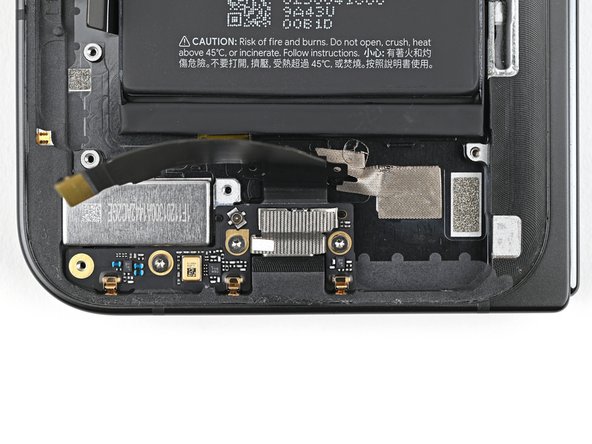
Use a Torx Plus 3IP driver to remove the three 2.6 mm‑long screws securing the USB-C port board.
-
-
-
Use a spudger to pry up the top right corner of the USB-C port board to unclip it from the frame.
-
-
-
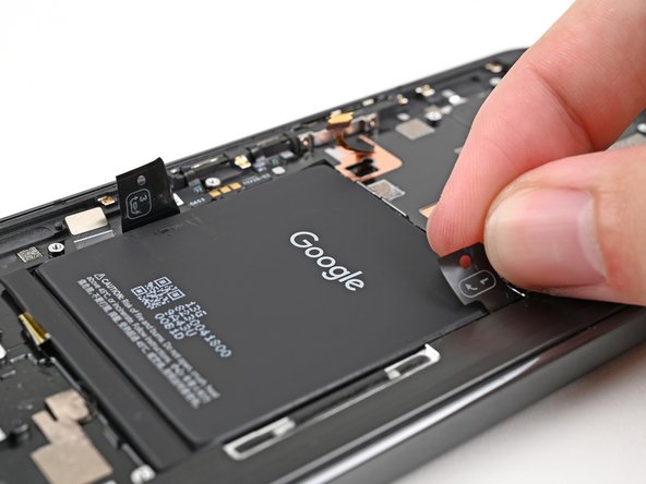
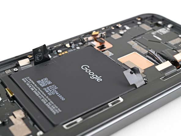
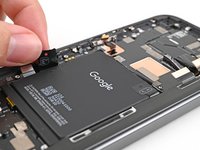
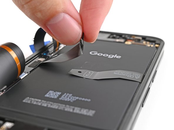
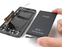
Use your fingers to peel up the two edges of the pull tab on the base battery.
-
-
-
Unfold your phone and flip it so the inner screen is facing upward.
-
Use a hair dryer, or a heat gun, to heat the section of inner screen behind the base battery until the its barely too hot to touch.
-
-
-
Fold your phone and turn it so the base battery is facing up.
-
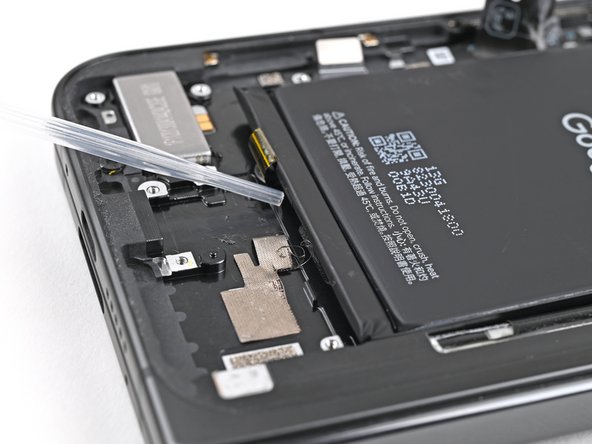
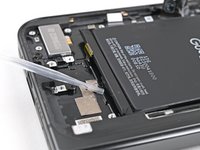
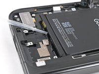
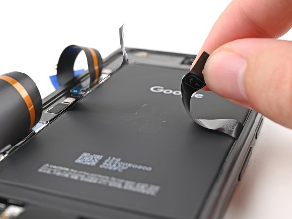
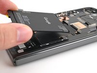
While holding the right pull tab, slide the left pull tab toward the top edge of the battery to separate the top section of adhesive.
-
-
-
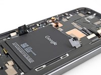
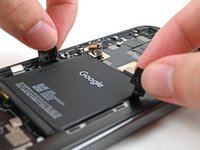
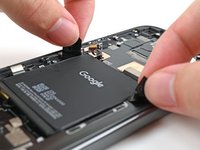
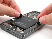
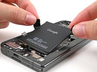
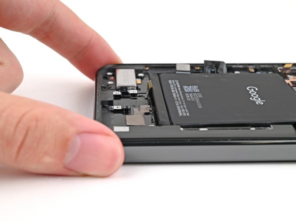
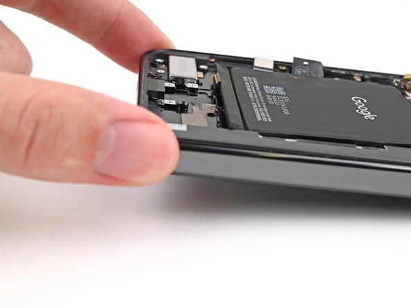
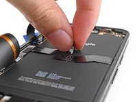
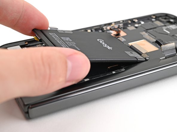
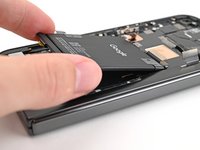
Grip the ends of the plastic pull tabs with your fingers.
-
Pull straight up with constant, steady force to separate the adhesive under the battery. Work slowly and let time do the work for you until the adhesive separates.
-
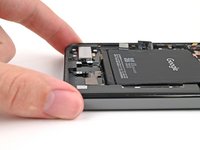
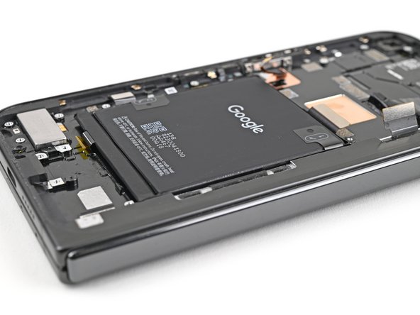
Remove the base battery.
-
-
-
Apply a few drops of high concentration (>90%) isopropyl alcohol under the bottom edge of the base battery.
-
-
-
Lift the bottom edge of the phone to let the isopropyl alcohol flow under the battery.
-
Wait one minute for the alcohol to soften the adhesive.
-
-
-
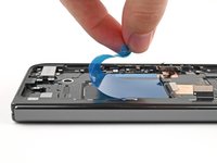
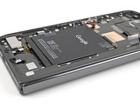
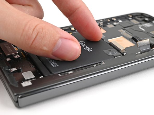
Apply a suction cup to the center of the base battery.
-
While securing the phone with one hand, pull up on the suction cup with strong, steady force to separate the base battery from the frame.
-
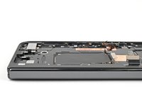
Remove the base battery.
-
-
-
Use a hair dryer, or a heat gun, to heat the vibrator until it's barely too hot to touch.
-
-
-
Insert one arm of a pair of angled tweezers in the notch at the bottom left corner of the vibrator.
-
Pry up with the tweezers to separate the adhesive securing it to the frame.
-
Remove the vibrator.
-
-
-
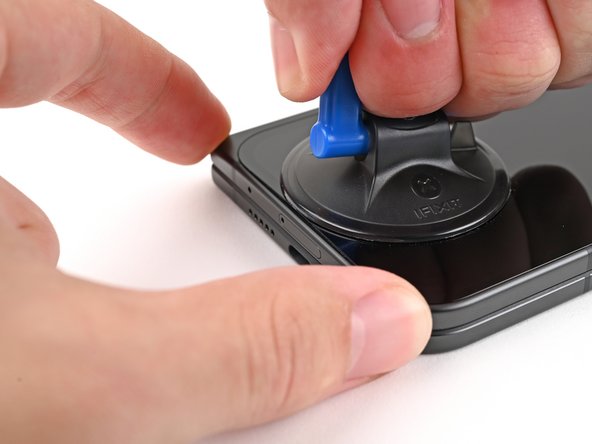
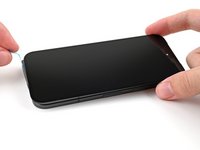
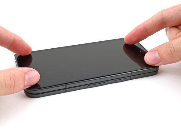
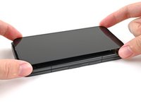
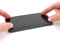
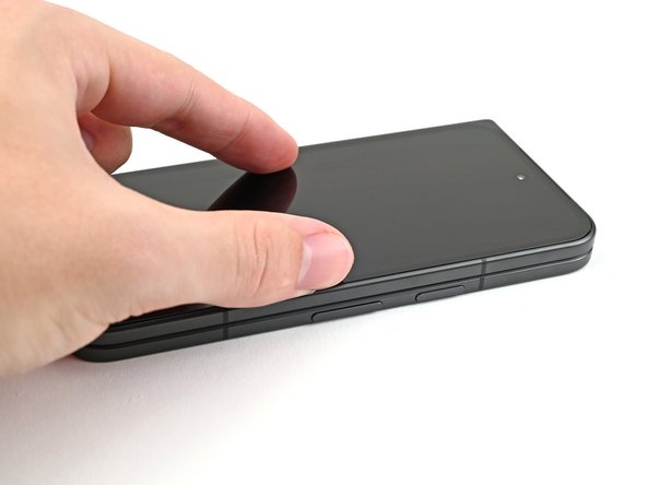
Apply a suction cup to the screen, as close to the center of the bottom edge as possible.
-
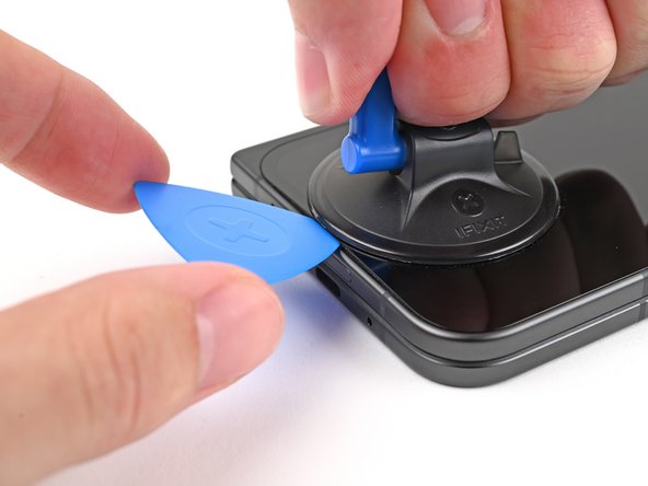
Pull up on the suction cup with strong, steady force to create a gap between the screen and the frame.
-
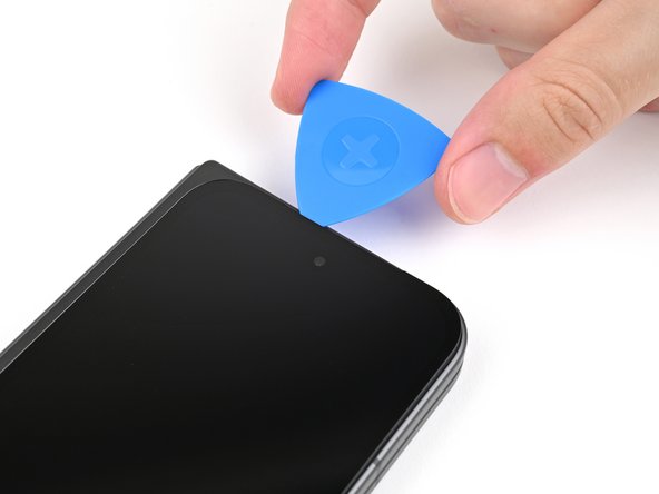
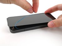
Insert an opening pick into the gap.
-
-
-
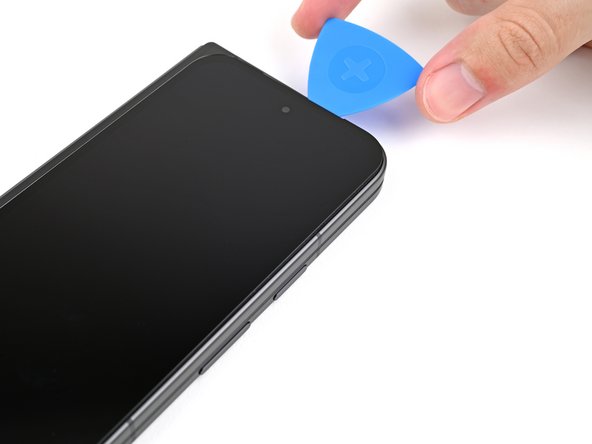
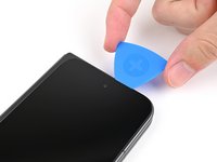
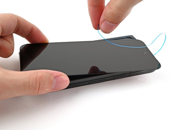
Slide the opening pick around the bottom right corner and up the right edge of the screen to separate the adhesive.
-
-
-
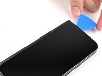
Pull the opening pick out so only the tip is under the screen.
-
Slide the opening pick across the top edge of the screen until you're past the front camera.
-
Push your pick to its original depth before continuing.
-
-
-
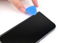
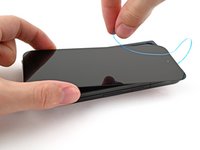
Slide the opening pick around the top left corner and stop about two‑thirds down the left edge of the screen.
-
-
-
Pull the opening pick out to a 2 mm depth and rotate the pick around the bottom left corner to separate the remaining adhesive.
-
-
-
Lift the right edge of the screen and swing it over the left edge of the phone, like opening a book.
-
Prop up the screen with your suction handle or a clean, sturdy object.
-
-
In diesem Schritt verwendetes Werkzeug:FixMat$36.95
-
Use a Torx Plus 3IP driver to remove the 2.2 mm‑long screw securing the display cable bracket.
-
-
-
-
Use a spudger, or your fingers, to lift the display cable bracket enough to access the press connector underneath.
-
-
-
Use the point of a spudger to pry up and disconnect the display cable press connector.
-
-
-
Use a Torx Plus 3IP driver to remove the 2.0 mm‑long screw securing the battery bracket.
-
-
-
Use tweezers, or your fingers, to move the battery bracket out of the way of the battery press connector.
-
-
-
Use the point of a spudger to pry up and disconnect the battery press connector.
-
-
-
Use tweezers, or your fingers, to remove the rubber block covering a screw on the top board.
-
-
-
Use a Torx Plus 3IP driver to remove the two 2.2 mm‑long screws securing the top interconnect cable bracket.
-
-
-
Use tweezers, or your fingers, to remove the top interconnect cable bracket.
-
-
-
Insert the point of a spudger under the top right corner of the top interconnect cable press connector, near the golden marker.
-
Pry up and disconnect the top interconnect cable press connector.
-
-
-
Use a Torx Plus 3IP driver to remove the two 2.2 mm‑long screws securing the bottom interconnect cable bracket.
-
-
-
Use tweezers, or your fingers, to remove the bottom interconnect cable bracket from the lower board.
-
-
-
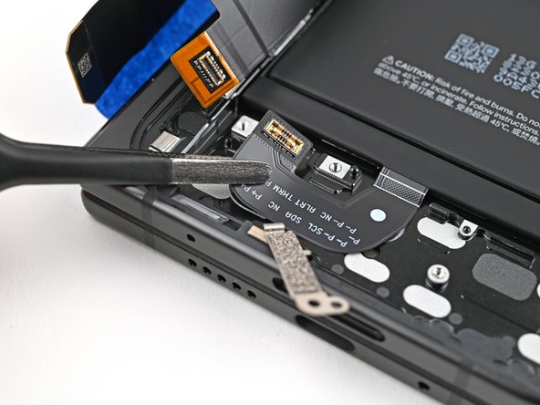
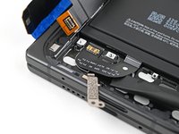
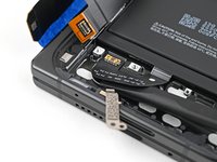
Insert a spudger under the right edge of the bottom interconnect cable press connector.
-
Pry up and disconnect the bottom interconnect cable.
-
-
-
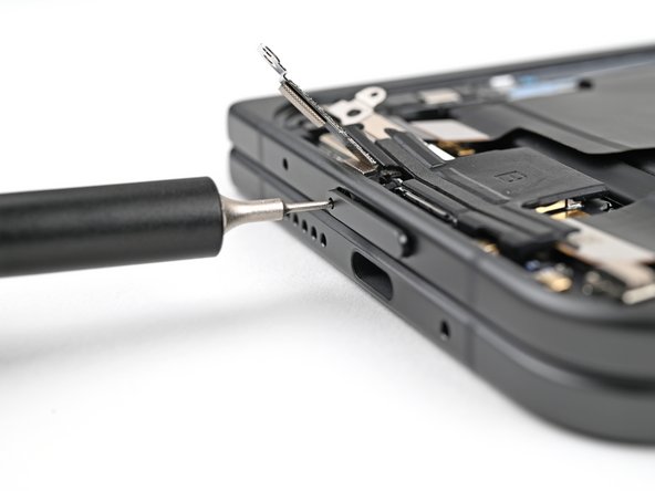
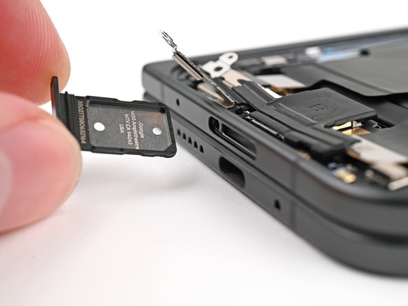
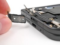
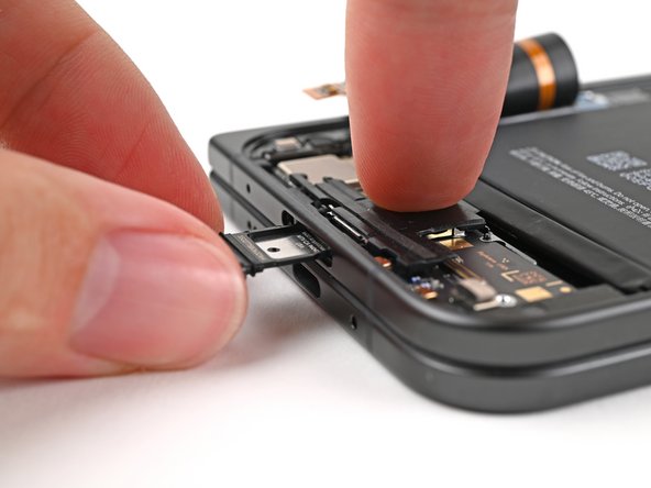
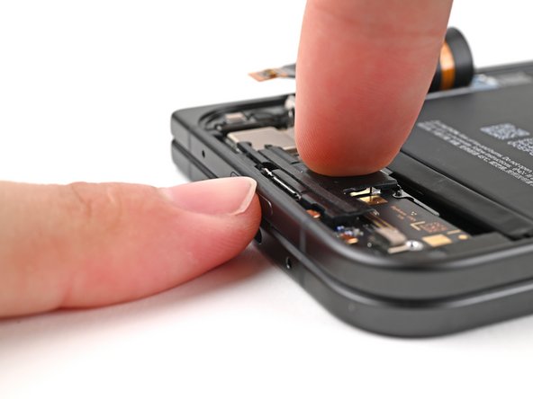
Insert a SIM eject tool, bit, or straightened paper clip into the SIM card tray hole and press firmly to eject it.
-
Remove the SIM card tray.
-
-
-
Slide the flat end of a spudger under the flip battery cable to separate the adhesive.
-
Use tweezers, or your fingers, to lift the flip battery cable connector and fully separate it from the frame.
-
-
-
Use your fingers to peel both edges of the flip battery pull tabs off the battery.
-
-
-
Unfold your phone and flip it so the inner screen is facing upward.
-
Use a hair dryer, or a heat gun, to heat the section of inner screen behind the flip battery (the side with the SIM card cutout) until it's barely too hot to touch.
-
-
-
Fold your phone and turn it so the flip battery is facing up.
-
Pull up on alternating sides of the pull tab to slice through the adhesive on the upper half of the flip battery, stopping once you get to the top edge.
-
-
-
Apply a few drops of isopropyl alcohol (>90%) under the bottom edge of the flip battery.
-
-
-
Lift the bottom edge of the phone to let the isopropyl alcohol flow under the battery.
-
Wait one minute for the alcohol to soften the adhesive.
-
-
-
Apply a suction handle to the center of the flip battery.
-
While securing the phone with one hand, pull up on the suction cup with strong, steady force to separate the flip battery from the frame.
-
Remove the flip battery.
-
-
-
Use a Torx Plus 3IP driver to remove the 2.2 mm‑long screw securing the top board.
-
-
-
Insert the flat end of a spudger under the bottom edge of the top board.
-
Twist the spudger to lift the top board enough to unclip it from the frame.
-
Remove the top board.
-
-
-
Congratulations on completing disassembly! The remaining steps will show you how to reassemble your device.
-
-
-
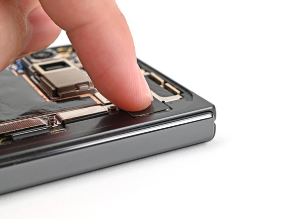
Press the top edge of the top board against the frame at a downward angle to engage its metal spring.
-
Press the board flat to the frame, making sure the screw holes are aligned.
-
-
-
Use a Torx Plus 3IP driver to install the 2.2 mm‑long screw securing the top board.
-
-
-
While holding the lower board in place, reinsert the SIM card tray.
-
-
-
Reconnect the bottom interconnect cable press connector.
-
-
-
Place the bottom interconnect cable bracket on the lower board and align its screw holes.
-
-
-
Use a Torx Plus 3IP driver to install the two 2.2 mm‑long screws securing the bottom interconnect cable bracket.
-
-
-
Reconnect the top interconnect cable press connector.
-
-
-
Place the top interconnect cable bracket on the top board and align its screw holes.
-
-
-
Use a Torx Plus 3IP driver to install the two 2.2 mm‑long screws securing the top interconnect cable bracket.
-
-
-
Place the rubber block over its spot on the top board and press it down.
-
-
-
Lay the flip battery bracket over the press connector and align the screw holes.
-
-
-
Use a Torx Plus 3IP driver to install the 2.0 mm‑long screw securing the battery bracket.
-
-
-
Use a spudger, or your fingers, to remove the old bottom left outer screen adhesive.
-
Use isopropyl alcohol (>90%) and a coffee filter or a microfiber cloth to remove any adhesive residue.
-
-
-
Before removing any liners, check if the bottom left outer screen adhesive matches the frame.
-
-
-
Peel the bottom left outer screen adhesive off its clear liner to expose the adhesive.
-
Put the adhesive into place on the frame.
-
-
-
Use the flat end of a spudger to press along the adhesive strip to adhere it to the frame.
-
-
-
Before removing any liners, check if the perimeter outer screen adhesive matches the frame.
-
-
-
Peel away the top half of the new adhesive strip from its clear liner and keep it folded.
-
-
-
Align the top half of the adhesive over the frame, using the corners as reference points.
-
Place the adhesive on the frame.
-
-
-
Use the flat end of a spudger, or your fingers, to press down the top edge of the adhesive and adhere it to the frame.
-
-
-
While peeling away the rest of the clear liner, slowly lay the rest of the adhesive over the perimeter of the phone.
-
-
-
Use the flat end of a spudger, or your fingers, to press down the rest of the adhesive and adhere it to the frame.
-
-
-
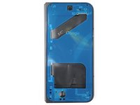
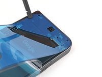
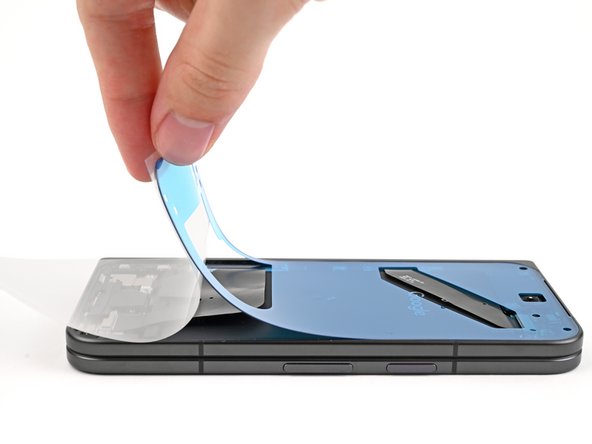
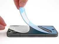
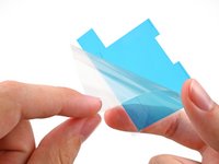
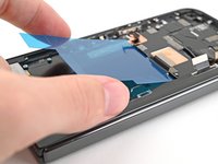
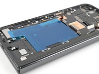
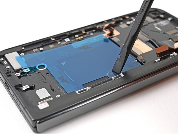
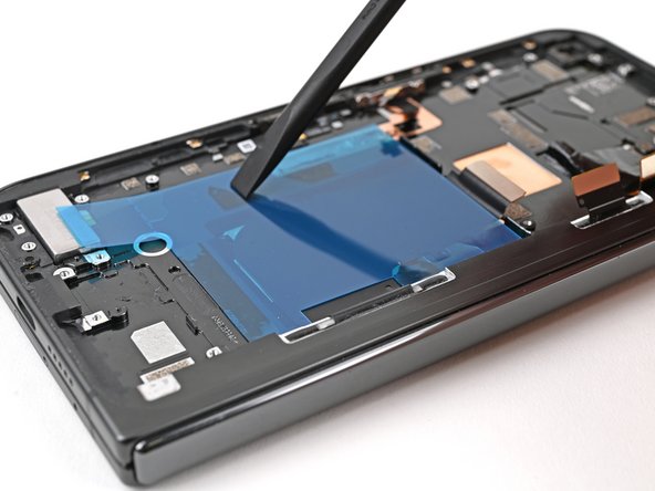
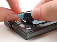
Use the tip of a spudger to pry up the segmented tab on the bottom left corner of the large blue liner.
-
-
-
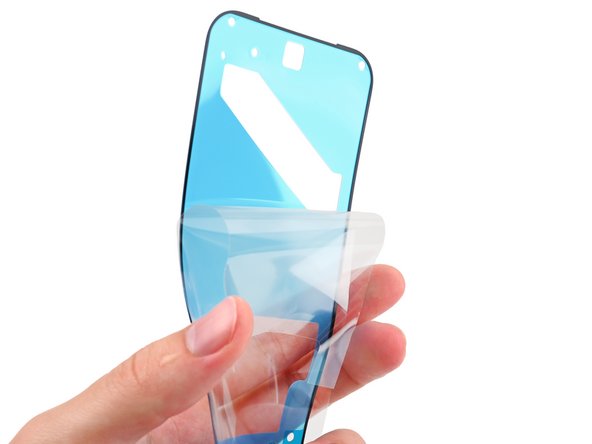
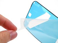
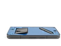
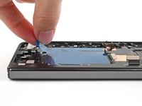
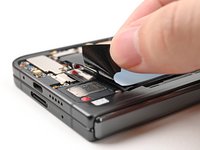
Lift the tab and peel off the large blue liner to expose the secondary liner.
-
-
-
Support the screen with your hand or prop it up on something sturdy.
-
Reconnect the outer screen cable press connector.
-
-
-
Reinsert the outer screen cable bracket clip under the frame and align its screw hole.
-
-
-
Use a Torx Plus 3IP driver to install the 2.2 mm‑long screw securing the display cable bracket.
-
-
-
Remove the blue liner from the bottom left outer screen adhesive strip.
-
While holding the screen above the frame, separate one of the secondary liner's pull tabs at the bottom left corner.
-
-
-
Still holding the screen, peel off the secondary liner to expose the adhesive.
-
-
-
Align the outer screen over the frame and press it into place.
-
-
-
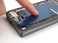
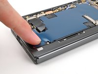
Press along the perimeter of the outer screen to adhere it to the frame.
-
Let the phone sit a few hours for the adhesive to cure.
-
-
In diesem Schritt verwendetes Werkzeug:Tesa 61395 Tape$5.99
-
Flip your phone over.
-
If your replacement inner screen assembly comes with adhesive pre‑installed over the vibrator cutout, remove its liner. Otherwise, use a thin double‑sided tape to replace the adhesive.
-
Align the vibrator over its cutout on the frame and press down to adhere it.
-
-
-
Use tweezers, or your fingers, to remove the old base battery adhesive from the frame.
-
Apply isopropyl alcohol (>90%) and use a coffee filter or microfiber cloth to clean any adhesive residue.
-
-
-
Before removing any liners, check that your base battery adhesive matches the size and shape of the cutout in the frame.
-
-
-
Peel off the adhesive strip from its clear liner.
-
Align the adhesive strip with the top edge of the base battery recess and press it onto the frame.
-
-
-
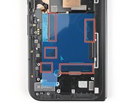
Use the flat end of a spudger, or your fingers, to press down the five adhesive strips and adhere them to the frame.
-
-
-
Align the new base battery with the top edge of the battery recess and press it to the frame.
-
-
-
Reinsert the USB-C port board into its recess in the frame.
-
-
-
Press the USB-C port board flat to the frame to re-engage the metal springs, making sure the alignment pegs fit into their holes in the board.
-
-
-
While holding the board in place, use a Torx Plus 3IP driver to install the three 2.6 mm‑long screws securing the USB-C port board.
-
-
-
Use tweezers, or your fingers, to remove the old adhesive under the USB-C port cable.
-
Peel the new USB-C port cable adhesive strip from its clear liner.
-
Align the adhesive strip over its spot in the frame and lay it down with the colored pull tab facing the right edge of the phone.
-
-
-
Use the flat end of a spudger, or your fingers, to press down the adhesive and adhere it to the frame.
-
Peel off the colored liner to expose the adhesive.
-
-
-
Use tweezers, or your fingers, to remove the bottom and top conductive fabrics or the loudspeaker cable adhesive if they're not intact.
-
-
-
Align the bottom loudspeaker conductive fabric on the underside of the loudspeaker.
-
-
-
Remove the conductive fabric from its clear and colored liners and lay it over its spot on the loudspeaker.
-
-
-
Use the flat end of a spudger, or your fingers, to press down the conductive fabric and adhere it to the loudspeaker.
-
-
-
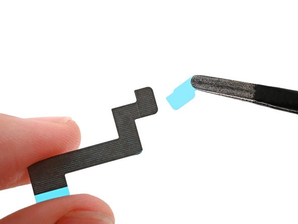
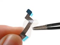
Peel the clear liner off the loudspeaker cable adhesive.
-
Align the adhesive over the loudspeaker cable and lay it down, making sure not to cover the hole in the cable.
-
-
-
Use your fingers to lightly pinch the cable and adhere the adhesive strip.
-
Remove the blue liner from the adhesive strip.
-
-
-
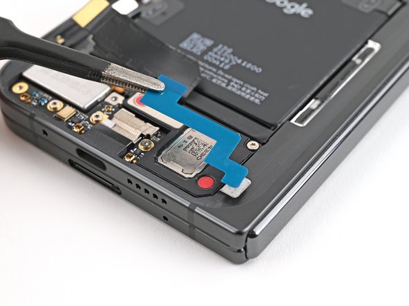
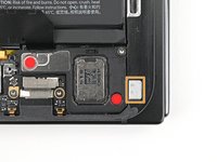
Align the hole in the loudspeaker cable over its peg on the frame.
-
Press down the cable with the tip of a spudger, or your finger, to adhere it to the frame.
-
-
-
While pressing the cable down, reinsert the loudspeaker at an angle into its recess and press it flat to the frame.
-
-
-
While holding the loudspeaker in place, use a Torx Plus 3IP driver to install the 2.6 mm‑long screw securing the loudspeaker.
-
-
-
Peel off the clear liner on the top loudspeaker conductive fabric.
-
Peel off the small colored liner covering the rounded corner of the fabric.
-
-
-
Align the rounded corner of the conductive fabric with the same‑shaped marking on the frame.
-
Lay the fabric down onto the frame and the loudspeaker.
-
-
-
Use the flat end of a spudger, or your fingers, to press down the conductive fabric and adhere it to the frame and loudspeaker.
-
-
-
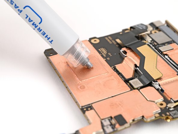
Apply small beads of thermal paste (five total) to the motherboard in the same locations as the old thermal paste.
-
-
-
Place the logic board back into its cutout in the frame, making sure no cables get trapped underneath it.
-
-
-
Use a Torx Plus 3IP driver to install the three screws securing the logic board:
-
One 2.2 mm‑long screw
-
Two 2.6 mm‑long screws
-
-
-
Use angled tweezers to push the side button cable back into its slot.
-
-
-
Flip the locking tab down and lightly press on it until it clicks into place.
-
-
-
Peel the clear liner off your replacement graphite sheet to expose the adhesive on the upper half.
-
Align the upper half of the graphite sheet over the logic board and lay it down.
-
-
-
Use your finger to press down the upper half of the graphite sheet and secure it to the logic board.
-
-
-
Remove the blue liner from the bottom of the graphite sheet to expose the adhesive underneath.
-
-
-
Drag your finger from the middle section of the graphite sheet to the adhesive spot on the loudspeaker to flatten the graphite sheet and adhere it.
-
-
-
Grip the pull tab at the top of the graphite sheet and peel off the remaining liner.
-
-
-
Reconnect the inner display cable and the top and bottom interconnect cable press connectors.
-
-
-
Reinsert the inner display cable bracket clip under its slot in the logic board and align the screw holes.
-
-
-
Use a Torx Plus 3IP driver to install the 3.0 mm‑long screw securing the inner display cable bracket.
-
-
-
Reinsert the bottom interconnect bracket clip under its slot in the frame and align the screw hole.
-
-
-
Use a Torx Plus 3IP driver to install the 3.0 mm‑long screw securing the interconnect cable bracket.
-
-
-
While holding the ultra wideband antenna out of the way, reinsert the ultra wideband bracket clip under its slot in the frame and align the screw holes.
-
-
-
Use a Torx Plus 3IP driver to install the two 3.0 mm‑long screws securing the ultra wideband bracket.
-
-
-
Remove the old adhesive and foam on the ultra wideband bracket and under the antenna.
-
Replace the corresponding adhesive and foam to the bracket and the frame.
-
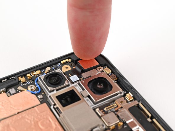
Press the ultra wideband antenna to the frame and re‑adhere it.
-
-
-
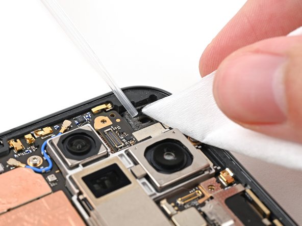
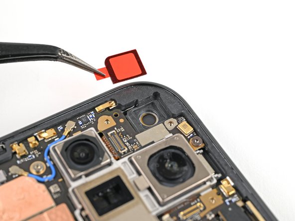
Use tweezers, or your fingers, to remove the old adhesive foam from the inner front camera cutout.
-
Use isopropyl alcohol (>90% or greater) and a coffee filter or lint‑free cloth to remove any adhesive residue.
-
-
-
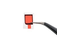
Peel the replacement inner front camera adhesive foam off its clear liner to expose the adhesive underneath.
-
Align the adhesive foam over the cutout in the frame so that the pull tab is facing the bottom of the phone.
-
Place the adhesive in the cutout.
-
-
-
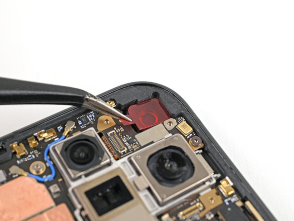
Use the tip of a spudger to press along the edges of the adhesive foam to secure it to the frame.
-
-
-
Use tweezers, or your fingers, to peel off the colored liner and expose the adhesive underneath.
-
-
-
While holding the inner front camera above its cutout, reconnect its press connector.
-
Lay the inner front camera in its cutout and press down to secure it to the adhesive.
-
-
-
Reinsert the inner front camera bracket clip under its slot in the logic board and align the screw holes.
-
-
-
Use a Torx Plus 3IP driver to install the two 2.6 mm‑long screws securing the inner front camera bracket.
-
-
-
Use tweezers to hold the antenna cable's connector in place over its socket and gently press down with your finger or a spudger until the connector snaps into place.
-
-
-
Place the vibrator bracket on the logic board and align its screw holes.
-
-
-
Use a Torx Plus 3IP driver to install the two 3.0 mm‑long screws securing the vibrator bracket.
-
-
-
Reconnect the USB-C port board cable press connector.
-
-
-
Reinsert the base battery bracket clip under its slot in the logic board and align its screw holes.
-
-
-
Use a Torx Plus 3IP driver to install the two 3.0 mm‑long screws securing the base battery bracket.
-
-
-
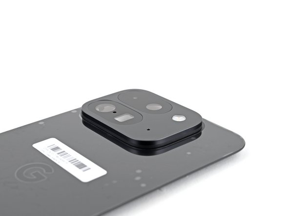
Use a spudger, or your fingers, to remove the old back cover adhesive.
-
Use isopropyl alcohol (>90%) and a coffee filter or a microfiber cloth to remove any adhesive residue.
-
-
-
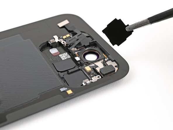
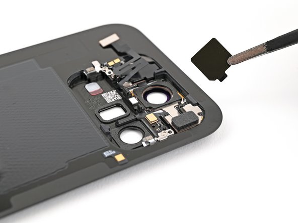
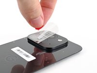
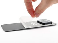
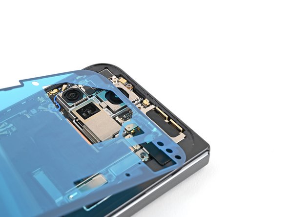
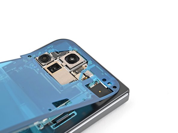
Use tweezers, or your fingers, to remove the three rear camera liners from the inside of your new back cover.
-
-
-
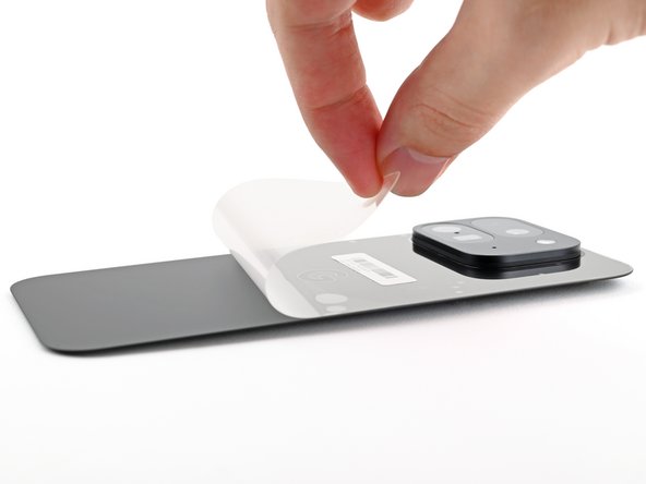
Before removing any liners, check if the adhesive matches the frame.
-
-
-
Peel away the top half of the new adhesive strip from its clear liner and keep it folded before continuing.
-
Align the top half of the adhesive over the frame, using the corners as reference points.
-
Place the adhesive on the frame.
-
-
-
Use the flat end of a spudger, or your fingers, to press down the top edge of the adhesive and adhere it to the frame.
-
-
-
While peeling away the rest of the clear liner, slowly lay the rest of the adhesive over the perimeter of the phone.
-
-
-
Use the flat end of a spudger, or your fingers, to press down the rest of the adhesive and adhere it to the frame.
-
-
-
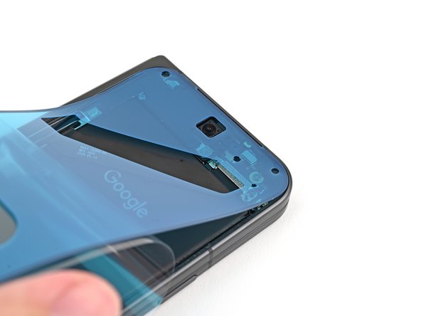
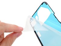
Use a spudger to pry up the segmented tab on the bottom right corner of the large blue liner.
-
Lift the tab and peel off the large blue liner to expose the secondary liner.
-
-
-
While holding the back cover or propping it up, reconnect the back cover cable.
-
-
-
Reinsert the top bracket clip under its slot in the logic board and align its screw hole.
-
-
-
Use a Torx Plus 3IP driver to install the 3.0 mm‑long screw securing the top bracket.
-
-
-
Use the tip of a spudger to pry up the segmented tab on the top right corner of the secondary liner.
-
-
-
Align the top edge of the back cover with the frame and press down to adhere it.
-
-
-
Press along the perimeter of the back cover to adhere it to the frame.
-
Let the phone sit a few hours for the adhesive to cure.
-


Congratulations on completing your repair!
For optimal performance, calibrate your newly installed batteries after completing this guide.
Take your e-waste to an R2 or e-Stewards certified recycler.
Repair didn’t go as planned? Try some basic troubleshooting, or ask our Google Pixel 9 Pro Fold Answers Community for help.
Rückgängig: Ich habe diese Anleitung nicht absolviert.
Eine weitere Person hat diese Anleitung absolviert.

