Einleitung
Diese Anleitung zeigt, wie ein defekter Akku im MacBook Air von 2019 ausgetauscht werden kann.
Um das Risiko eines Brandschadens zu verringern, solltest du dein MacBook anschalten und den Akku vor Reparaturbeginn ganz leer werden lassen. Ein Lithium-Ionen Akku kann sehr gefährlich werden, wenn er versehentlich angestochen wird. Wenn dein Akku aufgebläht ist, musst du besondere Vorsichtsmaßnahmen treffen.
Was du brauchst
-
-
Wenn dein MacBook unter BigSur v11.1 oder einer späteren Version läuft, lässt sich AutoBoot möglicherweise nicht deaktivieren. Arbeite zuerst normal weiter, trenne aber den Akku sofort ab, wenn du ins Innere des Gerätes hinein gekommen bist.
-
Entferne mit einem P5-Pentalobe-Schraubenzieher folgende Schrauben:
-
Zwei 7,9 mm Schrauben
-
Zwei 7,1 mm Schrauben
-
Sechs 2,6 mm Schrauben
-
-
-
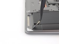
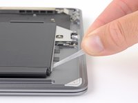
Zwänge deine Finger zwischen das Display und das Gehäuseunterteil und ziehe nach oben, so dass sich das Gehäuseunterteil vom Air ablöst.
-
Entferne das Gehäuseunterteil.
Are there any suggestions to removing the pressure fasteners more easily?
I used a suction cup to lift up the cover. I mean those to lift up an iPhone display. Worked like charm.
-
-
-
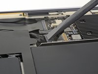
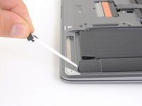
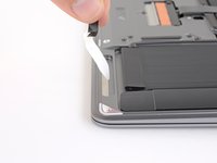
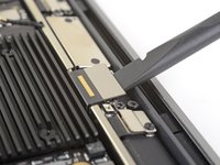
Ziehe den Aufkleber soweit vom Akkustecker zurück, dass der darunterliegende Stecker sichtbar wird.
-
-
-
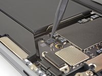
Schiebe den Akkustecker mit einem Spudger parallel zum Logic Board aus seinem Anschluss auf dem Logic Board heraus.
Before the battery can be fully disconnected, the battery disconnect button needs to be held down. There is a gold button just above the battery socket, along with a small LED much like the 12” machines. Once this has been held down and the LED has switched off it is safe to remove the battery.
This seems like an important step?
Also, seems like this should be done after the battery is disconnected, not before? Otherwise, wouldn’t the battery re-charge it?
What if the white LED dosent light up after pressing the yellow button again?
Iron05 -
I just performed this repair on my late 2018 mac air. I did click the gold button but saw no LED illuminated or otherwise. Question- after reassembly does the button get pressed again to connect the battery? Please clarify if this button is to be pressed and if it needs pressing again after the repair.
All said - I pressed again after the battery connector clicked, assembled the back and all worked perfectly. The original issue was one dead port (no charge, no communication). The battery charge lightening bold icon was acting funny too. Genuis bar guy in Naperville said it was likely a logic board too. But it was not. The port was apparently confusing the logic board with regards to the charge function. Thanks Adam for saving me $440 and sending my computer back to Apple. I am 71 yrs young - who says an old dog can’t learn new tricks with good training!!
I didn't see Aaron's comment before completing the battery replacement. Afterwards, the computer would not turn on despite multiple SMC reset procedures. Upon double-checking the comments I see the importance of pressing the gold button. I pressed the gold button before disconnecting the new battery, then pressed it again after reconnecting for good measure. Computer booted!
It would be good of iFixit to add this important step as most people probably don't open up every single comment on (seemingly) simple steps.
Seconding Corey's comment. If paid more attention to the comment section, I would have avoided 15-30 minutes of panic. (BTW I did not notice any LED, but the golden button was easy to find).
Where is the gold button? I replaced my battery and my laptop will not start
-
-
In diesem Schritt verwendetes Werkzeug:Tweezers$4.99
-
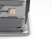
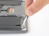
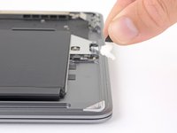
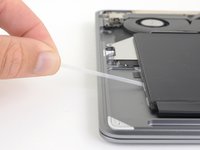
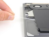
Nimm eine Pinzette und hebe die schwarze Zuglasche des Lautsprechers unten am rechten Lautsprecher soweit an, dass du sie mit deinen Fingern greifen kannst.
-
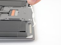
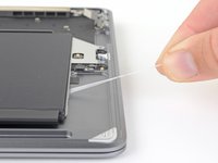
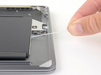
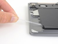
Fasse die Zuglasche an und ziehe sie langsam und behutsam unter dem rechten Lautsprecher hervor.
-
Wenn der Streifen reißt, dann lasse ihn so wie er ist und gehe zum nächsten Schritt über.
What do you do to get the speaker to stick once you put things back together? Are these adhesive strips reusable? If not, where can we get new ones?
The strips will tend to remain edhesive in some cases but if not just use some thin double sided adhesive tape of a similar width. I will not link because I am in Australia but it isn’t hard to find. I used some heat (100°C) and a plastic spudger to aid removal or a hair dryer on lower heat. Slow and steady, it’s not hard. The strips will almost certainly break.
-
-
-
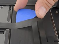
Schiebe die Spudgerspitze unter das Kabel zum rechten Lautsprecher und heble senkrecht nach oben, so dass der Lautsprecher abgetrennt wird.
Broke both speaker connectors by spudging straight up. Looks like they should slide apart like a normal zif.
Pulled straight up and broke both connectors.
What works for me with these is gently sliding one edge up off the pins first, then the other side.
This technique (one edge at a time) worked for me
-
-
-
Hebe die schwarze Zuglasche des Lautsprechers oben am rechten Lautsprecher soweit an, dass du sie mit deinen Fingern greifen kannst.
-
Fasse die Zuglasche an und ziehe sie langsam und behutsam unter dem rechten Lautsprecher hervor.
-
Erwärme den Lautsprecher, damit der Kleber darunter weich wird.
-
Schiebe vorsichtig einen Spudger oder ein Plektrum unter den Lautsprecher und trenne den Kleber auf.
This business of pulling the adhesive out (here and with the batteries) - at first it seems impossible, but persevere. Pull it really, really, slowly - it extends to around 30cm before it's all out. I applied a bit of heat with a heat gun (at least with the batteries) and after a few failed attempts got the hang of it. When it works, it's like magic and very satisfying, and much better than giving up and prising the part off with the adhesive in place.
-
-
-
Hebe den rechten Lautsprecher senkrecht von der Unterseite hoch und entferne ihn.
Step 5 the right speaker adhesive broken while removing, other end adhesive slipped out ok. But it's extremely hard to now lift up the battery, feels like I break something if I try harder.
This is not as easy as it sounds. Neither adhesive strip broke, but that bugger resists removal, because it is attached with adhesive tape to the bottom. Use different angles of attack to pry it up with steady force.
-
-
In diesem Schritt verwendetes Werkzeug:Tweezers$4.99
-
Hebe die schwarze Zuglasche unten am Lautsprecher mit einer Pinzette soweit an, dass du sie mit dem Finger fassen kannst.
-
Fasse die Zuglasche an und ziehe den Klebestreifen langsam und sorgfältig unter dem Lautsprecher hervor.
-
Wenn der Streifen reißt, dann lasse ihn, so wie er ist und gehe zum nächsten Schritt über.
Auf der rechten Seite ist mir der Klebestreifen gerissen. Habe dann auf der linken Seite nicht nur an der schwarzen Lasche gezogen, sondern mit Daumen und Zeigefinger am weißen Klebestreifen nachgegriffen. So kam er ohne Reißen raus.
-
-
-
Schiebe die Spudgerspitze unter das Kabel zum linken Lautsprecher und heble senkrecht nach oben, so dass der Lautsprecher abgetrennt wird.
-
Wenn der Stecker gelöst ist, dann schiebe das flache Ende des Spudgers unter das Kabel und trenne es aus der Klebeverbindung zum Logic Board ab.
-
-
-
Hebe die schwarze Zuglasche des Lautsprechers oben am linken Lautsprecher soweit an, dass du sie mit deinen Fingern greifen kannst.
-
Fasse die Zuglasche an und ziehe sie langsam und behutsam unter dem linken Lautsprecher hervor.
-
Erwärme den Lautsprecher, damit der Kleber darunter weich wird.
-
Schiebe vorsichtig einen Spudger oder ein Plektrum unter den Lautsprecher und trenne den Kleber auf.
-
-
-
Hebe den linken Lautsprecher senkrecht von der Unterseite hoch und entferne ihn.
-
-
-
-
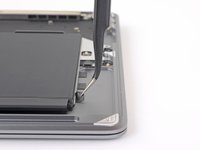
Entferne die beiden 1,4 mm Torx T3 Schrauben, mit denen die Halterung des Trackpad-Steckers befestigt ist.
-
Entferne die Halterung des Trackpad-Steckers.
My machine used T4 screws
Me too! I tried with T3 and it wasn’t working.
I stripped my screws trying to get them out with a t3 driver...
-
-
-
Heble den Stecker am Trackpadkabel mit dem flachen Ende des Spudgers hoch und löse ihn aus dem Abschluss heraus.
-
-
-
Schiebe die Spudgerspitze unter das Lautsprecherkabel und heble das Kabel zum Ablösen senkrecht hoch.
-
Schiebe das flache Ende des Spudgers bei gelöstem Stecker unter das Kabel und löse es aus der Klebeverbindung zum Logic Board.
-
-
-
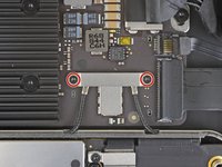
Entferne die beiden 1,3 mm Torx T3 Schrauben, mit denen die Halterung des USB-C-Anschlusses befestigt ist.
-
Entferne die Halterung des USB-C-Anschlusses.
There is no need to remove the logic board!!
Skip steps 16 through 28 and go to step 29 to release the trackpad cable from the battery. then follow steps to 30 through 33 to release the battery. The battery can be removed by slipping it counter-clockwise under the trackpad cable. The new battery can be slipped in place in the same way.
Much easier!!
Removing a few of the logic board screws allowed me to get the to right screw bracket under the logic board to give enough clearance as w98fxr mentioned.
This can be done, but it's very tight. Still, beats removing the logic board and the possibilities of breaking something in the process.
-
-
-
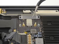
Heble den Stecker am USB-C-Kabel mit dem flachen Ende des Spudgers hoch und löse ihn aus seinem Anschluss auf dem Logic Board.
please reconsider removing the logic board and and usb-c connector as is recommended in the prior step. i had a very difficult time reconnecting the usb-c connector
It should be cautioned that this connector is very easily bent, meaning a bend in the length of the metal surface you press against to reconnect (or pry against for removal). Once bent it becomes very hard to establish a good connection.
-
-
-
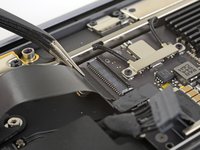
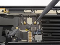
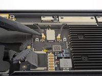
Klappe den Sicherungsbügel am ZIF-Anschluss der Audio-Platine hoch.
-
Schiebe das Kabel zur Audio-Platine aus seinem ZIF-Anschluss heraus.
-
-
-
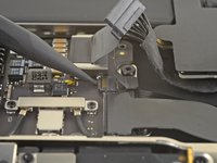
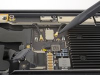
Klappe den Sicherungsbügel am ZIF-Anschluss des Lüfterkabels mit der Spudgerspitze hoch.
-
Schiebe das Lüfterkabel aus dem ZIF-Anschluss heraus.
-
-
-
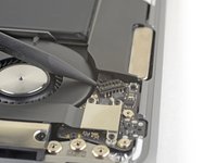
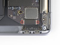
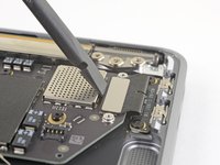
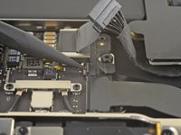
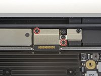
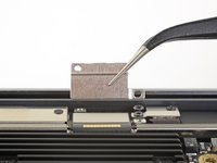
Entferne die beiden 1,4 mm Torx T3 Schrauben, mit denen die Halterung des Antennenkabels befestigt ist.
-
Entferne die Halterung des Antennenkabels.
These are T4 screws
The MBA I just finished with were T3. I'm fairly confident with my tools as I recently updated/upgraded nearly my entire set with WiHa. I should also mention the many tools acquired from iFixit over the years have all been were exceptional lasting years. There's no doubt iFixit would have been my source but a close friend went to work for WiHa. His discount(s) & being motivated to help him was a major impact. For anyone not having such an advantage IMHO tools from iFixit are one of the best values anywhere. Let's not forget; buying from iFixit will also help to push "Right to Repair" forward. Here in Minnesota Right to repair ALMOST PASSED. Many believe it will become law during the next session! I can't tell you how proud this would make me. I would obtain as many service manuals as possible and post them all online!!! What a great dream...
-
-
-
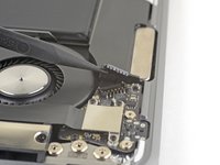
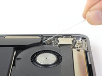
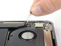
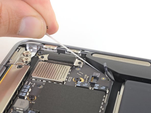
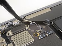
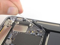
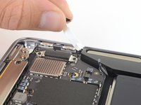
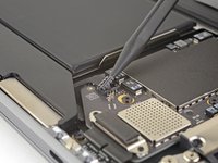
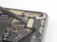
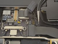
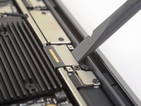
Setze die Spudgerspitze nahe am Stecker unter eines der Antennenkabel. Heble senkrecht nach oben und trenne das Kabel ab.
-
Wiederhole das Ganze für den anderen Stecker.
Be SUPER SUPER CAREFUL pulling off the gold WiFi antenna connectors! As described, use the spludger to press up the black cable just behind the metal connector. I tried to ping them off from the bottom of the gold connector where it clips into the socket on the motherboard and ended up pulling off the SMD sockets from the motherboard - huge and costly mistake that will probably render it useless.
-
-
-
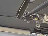
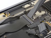
Entferne die beiden 1,5 mm Torx T3 Schrauben, mit denen die Halterung des Displaykabelsteckers befestigt ist.
-
Entferne die Halterung des Displaykabelsteckers.
-
-
-
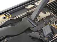
Heble den Displaykabelstecker mit dem flachen Ende des Spudgers hoch.
How do I reconnect display connector??
Just align the plug section of the display flex with the socket on the logic board and gently press it in until it locks in place. Do not force it but just ensure it’s correctly aligned before pushing it into the socket.
Pro tip: You can remove the two T5 screws on the LCD connector side (located to the right of the display connector and to the left of the heat shield). From there, tilt the whole skinny LCD board towards the logic board connector and gently pinch the connector in to the socket. Before laying the skinny board back down, screw in the shield from Step 15 so it doesn’t pop out of the socket again.
-
-
-
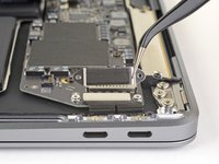
Entferne folgende Torx T5 Schrauben:
-
Eine 5,5 mm Schraube
-
Drei 2,6 mm Schrauben
-
Zwei 1,9 mm Schrauben
These are T5 Torx driver screws
Need torx 5 AND torx 4 driver here ;)
During re-assembly be soft when screwing in the logic board because those antenna plugs in Step 14 are quite awkward to pin back into their sockets and there is little leeway in the cables; to make this task a little easier in Step 14, secure the logic board loosely right up against the near outside edge; after re-connecting all the cables in Steps 16-9, return to Step 17 to firm up the logic board screws.
This tip was a huge help, hate these cables lol
The 5.5 mm screw goes into a hexagon standoff which may come off with the logic board being sanswiched beteen the 5.5 mm screw screw and the standoff like happened to me. Just something to be aware of. It also has a black rubber bumper over the screw which was not mentioned at all. It pulls straight off to give access to the screw.
On my board I needed to use T6 for all the screws except the rubber bumper for which I used a T7. I have a full set of small Torx drivers and tried for the best fit.
T5 fit best is all the screws on my machine
-
-
-
Schiebe behutsam ein Plektrum unter das Trackpadkabel und löse es aus der Klebeverbindung zum oberen Gehäuse.
-
-
-
Klappe den kleinen Sicherungsbügel am ZIF-Anschluss des Trackpadkabels hoch.
-
Ziehe das Trackpadkabel gerade aus seinem Anschluss heraus.
-
-
-
Schiebe behutsam ein Plektrum unter das Trackpadkabel und löse es aus der Klebeverbindung zum Akku.
-
-
-
Entferne die vier 2,5 mm Torx T3 Schrauben, mit denen der Akku befestigt ist.
-
-
In diesem Schritt verwendetes Werkzeug:Tweezers$4.99
-
Hebe die schwarze Zuglasche am Akku so weit mit der Pinzette an, dass du sie mit den Fingern fassen kannst.
-
Fasse die Zuglasche des Klebestreifens und ziehe den Klebestreifen langsam und sorgfältig unter dem Akku hervor.
-
Wenn der Klebestreifen reißt, dann lasse ihn so wie er ist und gehe zum nächsten Schritt über.
-
-
-
Wiederhole den vorigen Schritt für die anderen Klebestreifen an der gleichen Seite des Akkus.
-
Wenn einer der Streifen reißt, dann lasse ihn so, wie er ist, und gehe zum nächsten Schritt über.
-
-
-
Wiederhole die beiden vorigen Schritte für die drei Klebestreifen auf der anderen Seite des Akkus.
-
Gib behutsam ein paar Tropfen des Alkohols an jede Seite des Akkus an den vertieften Stellen, dort wo die Klebestreifen waren.
-
Lasse den Alkohol ein bis zwei Minuten einwirken.
-
Heble den Akku behutsam mit einem Plektrum vom oberen Gehäuse ab.
-
-
-
Entferne den Akku.
-
Kalibriere deinen neu eingebauten Akku: Lade ihn auf 100% auf und lasse ihn mindestens zwei weitere Stunden angeschlossen.Benutze dann dein Gerät normal, um den Akku zu entleeren. Wenn die Akkuwarnung erscheint, speichere ab und lasse den Laptop laufen, bis er von selbst ausgeht. Warte mindestens fünf Stunden und lade ihn ohne Unterbrechhung auf 100% auf.
-


Vergleiche dein Ersatzteil mit dem Originalteil — möglicherweise musst du fehlende Bauteile übertragen oder Schutzfolien vom Neuteil abziehen, bevor du es einbauen kannst.
Um dein Gerät wieder zusammenbauen, folge den Schritten in umgekehrter Reihenfolge.
Entsorge deinen Elektromüll fachgerecht.
Hat die Reparatur doch nicht den richtigen Erfolg gebracht? In unserem Forum findest du Hilfe bei der Fehlersuche.
Rückgängig: Ich habe diese Anleitung nicht absolviert.
33 weitere Personen haben diese Anleitung absolviert.
Besonderer Dank geht an diese Übersetzer:innen:
100%


Diese Übersetzer:innen helfen uns, die Welt zu reparieren! Wie kann ich mithelfen?
Hier starten ›

10 Kommentare
Great repair guide but the logic board screws are Torx T5 (not T4) at Step 25 of guide
Thanks! I would never have guessed everything that needed to be done without this guide. Man, I HATE the tiny, tiny screws. Lost one even after sticking all the screws to tape, just in case. :( Took the full hour to put in in, but the new battery is charging like new.
Be SUPER SUPER CAREFUL pulling off the gold WiFi antenna connectors! As described, use the spludger to press up the black cable just behind the metal connector. I tried to ping them off from the bottom of the gold connector where it clips into the socket on the motherboard and ended up pulling off the SMD sockets from the motherboard - huge and costly mistake that will probably render it useless.
Bonjour curieusement la batterie de mon macbook AIR A1932 est pas tout a fait la même il y a une petite carte en plus entre la batterie en elle même et le connecteur ,si je veux changer celle-ci dois je acheter exactement la même
Bonjour @gedfr en cas de doute sur la compatibilité, le plus simple est de contacter le fournisseur de la pièce. Si vous souhaitez acheter la batterie chez iFixit, c'est le support@ifixit.com (pour la boutique américaine) ou le eustore@ifixit.com (pour la boutique européenne et française). Ce sera un plaisir de vous aider ! Bien à vous, Claire
@claireMiesch ahhh super merci je savais qu’il y avais une boutique française , un précieux renseignement car j’ai plusieurs MAcBook à réparer. Dont un avec écran totalement exploser ,
@gedfr Avec plaisir et bonnes réparations :)
Reassembly instructions which just state “follow the above steps in reverse order” is not super helpful since there is now a lot of components which may not have any functional adhesive. Since half the guide is telling us how to carefully remove everything Apple taped in, how about a recommendation on at least the specification of tape to use when reassembling?
Obviously some of it can be reused (hopefully) but for the rest?
If the first thing you do is disconnect the battery, is it really an issue if you don’t (or can’t) disable auto-boot?
maccentric - Antwort
I agree, why disable Auto-Boot when the lid is closed and the battery is disconnected immediately? – I've never had an issue since 2016 when the feature was introduced.
stevebsiegel - Antwort
On my machine, the longest two screws were in the corners, while the other two long screws were in the middle. Perhaps previous service in the past had them replaced into the wrong place? In any case, the longest screws do seem to fit in either place. I guess 0.8mm is not very much of a difference. Seems like poor design if they could have used one size of screw.
johann beda - Antwort
Just did one, and it also had longest screws in the corners.
maccentric -
Just did another, and the long ones were in the middle. Definitely poor design and quality control.
maccentric -