
Dell Inspiron 700m Fan & Thermal Compound Replacement

Einleitung
Zu Schritt 1 der AnleitungIf your 700m is prone to overheating, a new fan and some upgraded thermal paste may be just the ticket. You can also use this guide to access the fan for cleaning.
Was du brauchst
Fix Kit
Dieses Kit enthält alle Ersatzteile und Werkzeuge, die für die Anleitung benötigt werden.

Ersatzteile


Werkzeuge


Mehr anzeigen …
-
-
Before you begin, make sure the 700m is powered off.
-
Unplug the power cable.
-
Flip the 700m over and remove the battery.
-
Slide the battery release switch toward the center of the 700m, and then pull the battery free from the back.
-
-
-
Remove the three Phillips screws securing the hard drive cover.
-
Remove the hard drive cover and set it aside.
-
-
In diesem Schritt verwendetes Werkzeug:Tweezers$4.99
-
Remove the two Phillips screws securing the hard drive retaining bracket.
-
Remove the retaining bracket using your fingers or a pair of tweezers.
-
-
-
Pull up on the blue tab to lift the hard drive up at an angle.
-
Remove the hard drive.
-
-
-
Remove the two Phillips screws securing the wi-fi cover.
-
Remove the wi-fi cover and set it aside.
-
-
-
You may find two Phillips screws located above and below the wi-fi card slot. If these screws are present, remove them now.
-
-
-
Using the flat end of a spudger, disconnect the black and white wi-fi antenna wires by prying them up from the wi-fi card.
-
-
-
Two clips secure the wi-fi card in place, one on either side. Using your fingers, spread the clips away from the wi-fi card.
-
Lift the wi-fi card to an angle of about 30 degrees and slide it out.
-
-
-
Slide the release switch for the optical drive toward the back of the 700m, and remove the optical drive.
-
-
-
Remove seven Phillips screws from the bottom of the 700m.
-
This screw is shorter in length than the others.
-
-
-
Rotate the 700m 90 degrees clockwise, and identify the VGA port.
-
Using a 5 mm socket, remove the two hex nuts located on either side of the VGA connector.
-
-
-
Flip the 700m over, and remove the two Phillips screws located on the back near the display lid hinges.
-
-
-
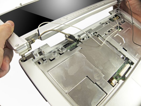
Open the display and lay it down flat.
-
Beginning from the left side, use the flat end of a spudger to gently pry up the plastic trim that runs along the top of the keyboard. Remove the trim.
-
-
-
Tilt the top of the keyboard up at an angle and push the keyboard toward the back of the 700m, freeing the tabs along the bottom.
-
-
-
Tilt the bottom of the keyboard up at an angle, and use the pointed end of a spudger to disconnect the ribbon cable by pushing open the clips on either side.
-
Remove the keyboard.
-
-
-
Using your fingers and the tip of a spudger, gently loosen the wires and free them from their channels.
-
-
-
Pull the lower ends of the black and white wi-fi antenna wires through the hole near the middle of the 700m.
-
-
-
Using your fingers or a pair of tweezers, disconnect the speaker cable by pushing the connector toward the back of the 700m.
-
-
-
Identify the display inverter cable, which connects to the motherboard just above and to the right of the speaker cable connector.
-
Use the flat end of a spudger to disconnect the inverter cable by prying up on each side of the connector.
-
-
-
Identify the LCD cable, which connects to the top left side of the motherboard.
-
To disconnect the LCD cable, grab the pull tab on the top of the connector and pull it straight up from the motherboard.
-
It may be helpful to use a spudger or small flathead screwdriver for extra leverage.
-
-
-
Remove the two Phillips screws securing the inner RAM cover.
-
Tilt the right side of the RAM cover up at an angle and remove it.
-
-
-
Two clips secure the RAM module in place, one on either side. Using your fingers, spread the clips away from the RAM module.
-
Lift the RAM module to an angle of about 30 degrees and slide it out.
-
-
-
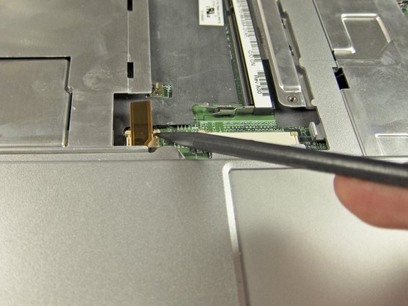
Use the pointed end of a spudger to disconnect the touchpad ribbon cable connector by pushing open the small clips on either side.
-
-
-
Beginning from the top left, use your fingers to separate the upper case from the 700m by pulling it straight up.
-
Remove the upper case.
-
-
-
Remove the two Phillips screws from the top right edge of the motherboard.
-
-
-
Swing the right side of the motherboard up at an angle, and then slide the motherboard to the right to remove it.
-
-
-
Flip the motherboard over and lay it down flat.
-
Disconnect the fan wire from the motherboard by pulling the connector straight up.
-
-
-
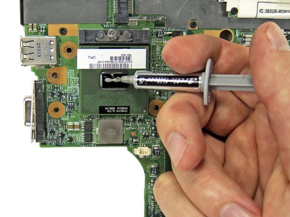
If you are replacing either the fan or heat sink, but not both, remove the three Phillips screws securing the fan to the heat sink, and then remove the fan.
-
If you are re-using the fan, use compressed air to blow the fan blades and airflow channel clean of dust and debris.
-
-
-
Now use our guide on Wie trage ich Wärmeleitpaste am besten auf to clean your heat sink and add some spicy hot thermal paste!
-


To reassemble your device, follow these instructions in reverse order.
To reassemble your device, follow these instructions in reverse order.
Rückgängig: Ich habe diese Anleitung nicht absolviert.
2 weitere Personen haben diese Anleitung absolviert.


2 Kommentare
A very well detailed instruction , very well presented, easy to follow and step by step pictures reference for the amateur handy husband . Thanks for the acquired knowledge you have given.