Einleitung
Folge dieser Anleitung, um ein defektes/beschädigtes LCD einer Nintendo Switch Lite auszutauschen.
In der Switch Lite sind JIS-Schrauben verbaut, zur Not passen aber auch Bits für Kreuzschlitzschrauben. Sei aber sehr vorsichtig und beschädige die Schraubenköpfe nicht. Die Bits von iFixit können auch für JIS-Schrauben verwendet werden.
Hinweis: Der Ausbau der Joysticks oder Tasten ist nicht notwendig, aber dies macht diese Reparatur um ein Vielfaches einfacher.
Hinweis: Diese Anleitung gilt nur für das LCD alleine. Wenn du die Displayeinheit, also Display mit daran befestigtem Touchscreen austauschen willst, dann verwende [lguide|156978|diese Anleitung|new_window=true]. Falls das Display gerissen oder zersprungen ist, aber noch funktioniert, folge stattdessen der Anleitung zum Austausch des Touchscreens.
Hinweis: Für diese Reparatur ist es notwendig sowohl das Abschirmblech als auch den Kühlkörper zu entfernen. Die alte Wärmeleitpaste muss von diesen Bauteilen sowie der CPU sauber entfernt werden und neu aufgetragen werden, bevor das Abschirmblech und der Kühlkörper wieder eingebaut werden.
Was du brauchst
-
In diesem Schritt verwendetes Werkzeug:Magnetic Project Mat$19.95
-
Entferne die vier 6,3 mm Y00 Schrauben, mit denen die Rückseite befestigt ist.
-
-
-
Nimm einen JIS 000 Schraubendreher/Bit oder ein Original PH000 Bit von iFixit und entferne folgende JIS-Schrauben, mit denen die Rückseite oben und unten befestigt ist:
-
Zwei 3,6 mm lange Kreuzschlitzschrauben an der Oberkante des Gerätes
-
Zwei 3,6 mm lange Kreuzschlitzschrauben an der Unterkante des Gerätes
-
Passe auf, dass die Schraubenköpfe nicht rundgedreht werden. Drücke das Werkzeug fest nach unten und arbeite langsam. Wenn die Schrauben nicht herauskommt, dann versuchen es mit einem anderen Bit.
I accidentally stripped the back screw and now I can't open it. I removed all the other screws. What should I do?
-
-
-
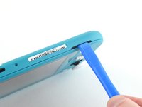
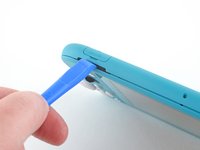
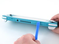
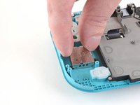
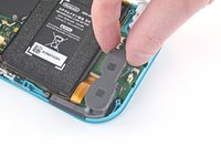
Setze ein Öffnungswerkzeug in die linke Öffnung für den Lautsprecher an der Unterseite des Geräts ein.
-
Verdrehe das Werkzeug, so dass sich die Rasten lösen, mit denen die Rückseite befestigt ist.
-
-
-
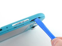
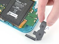
Schiebe das Öffnungswerkzeug um die untere linke Ecke herum, so dass sich die Rasten auf der linken Seite des Geräts lösen.
-
-
-
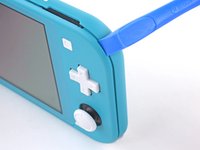
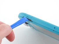
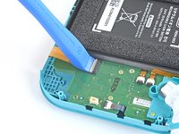
Setze ein Öffnungswerkzeug in die rechte Öffnung für den Lautsprecher an der Unterseite des Geräts ein.
-
Verdrehe das Werkzeug, so dass sich die Rasten lösen, mit denen die Rückseite befestigt ist.
-
-
-
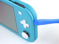
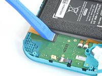
Schiebe das Öffnungswerkzeug um die untere rechte Ecke herum, so dass sich die Rasten auf der rechten Seite des Geräts lösen.
-
-
-
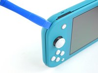
Schiebe das Werkzeug weiter am Spalt an der Oberseite des Geräts entlang und heble die Rasten auf.
-
-
-
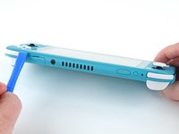
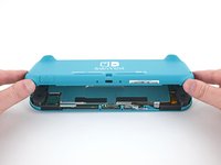
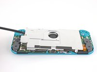
Hebe die Unterkante der Rückseite an und klappe sie wie ein Buch auf.
-
Entferne die Rückseite.
-
-
-
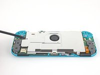
Nimm einen JIS 000 Schraubendreher/Bit oder ein Original PH000 Bit von iFixit und entferne folgende vier JIS-Schrauben:
-
drei 3,1 mm Schrauben
-
eine 4,5 mm Schraube
There are four screws instead of three mentioned
With how easy it seems to be to do serious damage with the next few steps, I figured I'd say that realistically you can skip steps 9-13 when doing this repair. While they provide a bit of extra security by disconnecting the battery, the left stick is completely accessible and replaceable without touching the heat shield or anything underneath (And steps 17 and 18 disconnect power from the daughter board regardless).
i stripped a &&^&^$^ screw
Well I actually removed the screw right next to the 4.5 screw. I did not realize it till my son showed me why the plate wouldn't release. Ha ha, it's funny now but yeah not a big deal. I could have bent it badly assuming I took all screws out though. For anyone reading this before going in. 👍
-
-
-
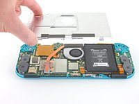
Hebe mit dem Finger oder einem Spudger das Abschirmblech hoch und entferne es aus dem Gerät.
-
Entferne das Abschirmblech.
What type of Thermal Paste would you guys recommend? I clicked on the picture but nothing.
Personnaly i use some Mx-6 from Artic, really good quality/price, never have to complain.
Nothing -
-
-
-
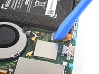
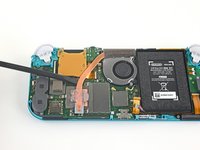
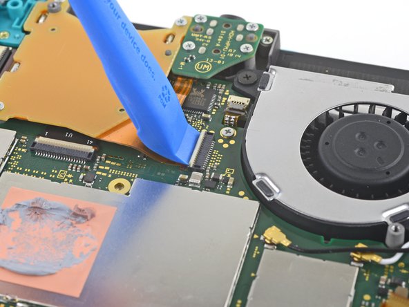
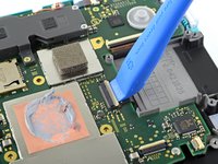
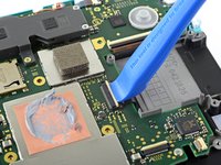
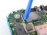
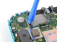
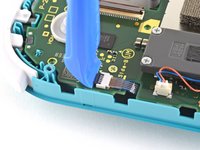
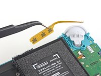
Klappe den kleinen, scharnierartigen Sicherungsbügel am ZIF-Verbinder des Verbindungskabels auf der Hauptplatine mit dem Fingernagel oder einem Öffnungswerkzeug hoch.
The clip broke off when trying to remove this cable. Audio only works through headphones and the display now won’t turn on after the clip broke. Does anyone know where I could get a clip or how I could fix it without it?
Mi è successa la stessa cosa è non so come ripararla! Chissà se c’è un modo!
-
-
-
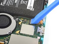
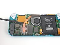
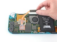
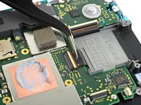
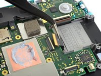
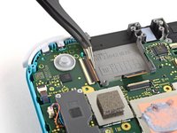
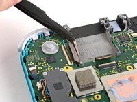
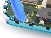
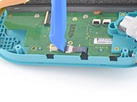
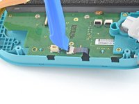
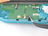
Schiebe das Verbindungskabel mit Hilfe einer Pinzette aus dem Anschluss auf der Hauptplatine heraus.
I turned the unit off beforehand, I used tweezers just like the instructions said (ifixit branded) , my device sparked and now it won’t turn back on
The flap came off is it important or is there a way t fix it?
We're you able to get it working without the white flap? My screen is not working after putting it back together and i noticed this white flap was falling off
Did you get it working without the white flap? Everything on the switch works fine except for audio going through headphones and the display not turning on.
do not use metal sharp pointed tweezers! you will rip your ribbon cable. Use the inside of a Bic type pen or something else dull and plastic to pull the cable away by putting the pen part where the first bend is.
Maybe tape the Tweezers or smear some hot glue on them to insulate them to save you time and money.
Maybe put all the Warnings at the start of the guide as well. We fix it geeks tend to get excited when fixing things 😁
-
-
-
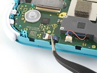
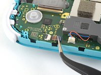
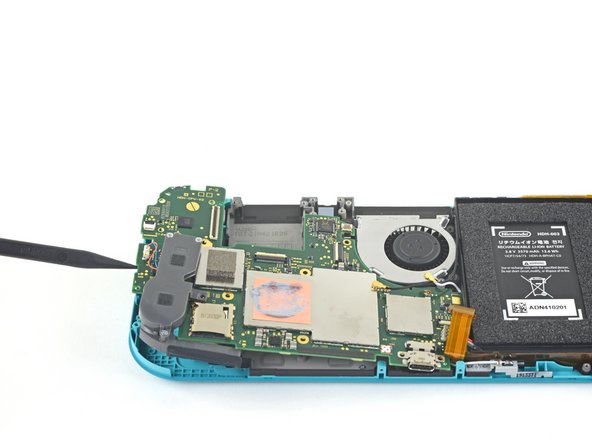
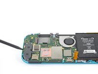
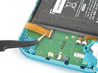
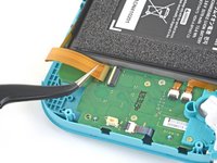
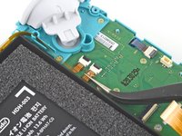
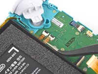
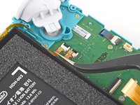
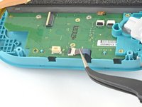
Heble den Akkuanschluss mit der Spudgerspitze gerade nach oben aus seinem Anschluss auf der Hauptplatine heraus.
Caution the connector may not be properly soldered onto the motherboard. For me it snapped off the pins and now have to find a place to get that fixed if even possible. may have bricked it.
Yup, broke the connector right off the motherboard. Thanks, ifixit -_-
I backed out when I reached this point. I couldn't risk damaging it. Do u just need to pull it up? Did you mean that it might have been soldered shut below?
You should just need to pull straight up, but make sure you’re pulling on the wires or the gray plug—do not pull on the black socket or it can snap off of the motherboard.
With how easy it seems to be to do serious damage at this point, I figured I'd say that realistically you can skip steps 9-13 when doing this repair. While they provide a bit of extra security by disconnecting the battery, the left stick is completely accessible and replaceable without touching the heat shield or anything underneath (And steps 17 and 18 disconnect power from the daughter board regardless).
just broke my connector... ifixit PLEASE put a warning on how fragile the solder on this connector is.
Note for this step, you do not need to apply a lot of force. I used two tools here: small screwdriver to hold down the black base, and one side of fine-tipped tweezers to get under all 3 wires. Gently, push down on the tweezers to push the wires upwards, which should force the gray connector up and off the base. It did not take a lot of force. Take your time and it will be fine. Again, like others have said, do NOT pull or pry up the black base.
-
-
-
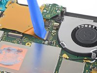
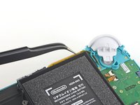
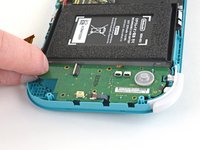
Entferne den leicht verklebten Schaumstoff am Lüfter mit dem flachen Ende eines Spudgers oder mit deinem Finger.
When reassembling, the foam may fold down between the fan and heatsink, blocking airflow. Gently lift the foam back up on top of the fan. The adhesive film should hold the foam together.
Is removing the heat sink absolutely necessary?
It’s not necessary, but it makes it much easier to remove and replace the game card reader, since the heat sink partially covers the connector.
Not really…….. I never remove it. It slides out quite easily once disconnected.
-
-
-
Nimm einen JIS 000 Schraubendreher/Bit oder ein Original PH000 Bit von iFixit und entferne die drei 3 mm JIS Schrauben, mit denen der Kühlkörper an der Hauptplatine befestigt ist.
Non le tre ventole ma le tre viti
Grazie per avercelo segnalato! Ho apportato la modifica. iFixit è una wiki, quindi ogni utente può modificare le pagine: se trovi altri errori in futuro, sentiti libero di fare la modifica tu stesso!
-
-
-
Hebe den Kühlkörper mit dem Finger oder einem Spudger von der Hauptplatine hoch und entferne ihn.
16.5 remove cartridge / headphones jack……….
My kit did not come with thermal paste..
-
-
-
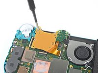
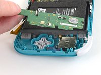
Klappe den kleinen, scharnierartigen Sicherungsbügel am ZIF-Verbinder des Kabels zum Game Card Leser mit dem Fingernagel oder einem Öffnungswerkzeug hoch.
-
-
-
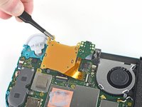
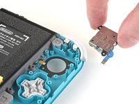
Nimm einen JIS 000 Schraubendreher/Bit oder ein Original PH000 Bit von iFixit und entferne die sieben 3,1 mm JIS-Schrauben, mit denen der Game Card Leser und die Kopfhörerbuchse befestigt sind.
-
-
In diesem Schritt verwendetes Werkzeug:Tweezers$4.99
-
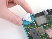
Bewege den Game Card Leser mit einer Pinzette oder deinen Fingern nach links, so dass das Kabel aus seinem Anschluss herausgleitet.
-
Entferne den Game Card Leser und die Kopfhörerbuchse.
-
-
-
Nimm einen JIS 000 Schraubendreher/Bit oder ein Original PH000 Bit von iFixit und entferne die beiden 4,5 mm JIS-Schrauben, mit denen die Baugruppe der rechten Trigger-Taste an der Hauptplatine befestigt ist.
I think a whole step to remove the game card reader and speaker jack was skipped here…
yes, just found that sadly these comments do not show unless we click on the , which is unhelpful
also, you need to remove the left trigger button
-
-
In diesem Schritt verwendetes Werkzeug:Tweezers$4.99
-
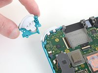
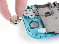
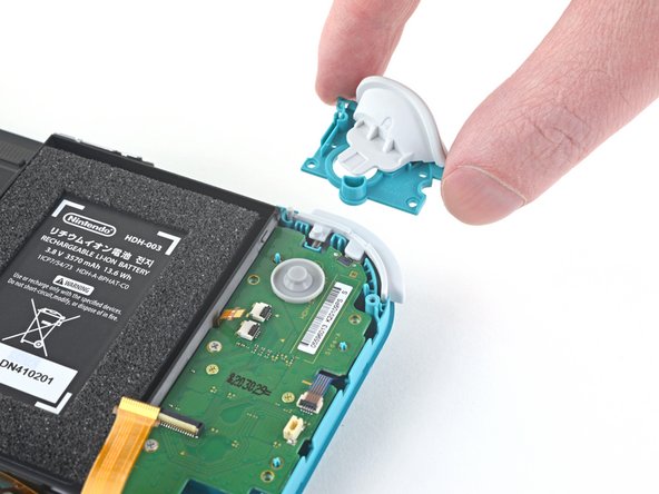
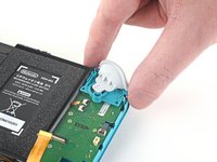
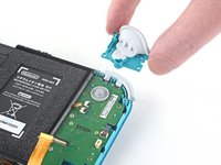
Wenn das Gummipad nicht an der rechten Trigger-Taste hängen geblieben ist, dann hole es jetzt mit einer Pinzette oder den Fingern heraus.
-
-
-
-
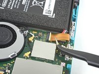
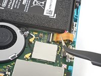
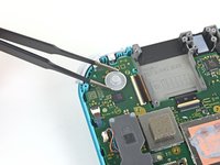
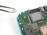
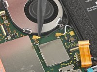
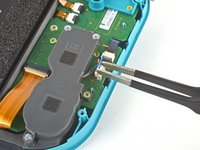
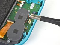
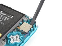
Heble das schwarze Antennenkabel mit der Spudgerspitze gerade nach oben aus dem Anschluss auf der Hauptplatine hoch.
-
Wiederhole das Ganze für das weiße Antennenkabel.
-
-
-
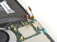
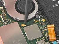
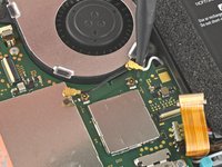
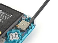
Klappe den kleinen, scharnierartigen Sicherungsbügel am ZIF-Verbinder des Lüfterkabels mit einem Öffnungswerkzeug oder dem Fingernagel auf.
-
-
-
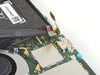
Schiebe das Lüfterkabel mit einer Pinzette aus seinem Anschluss auf der Hauptplatine heraus.
There’s a step missing after this to remove the screws that hold the orange game cartridge slot. Those 7 screws have to be undone and the ribbon unclipped first before moving on to the next step.
Good Looking out!
-
-
-
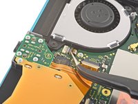
Klappe den kleinen, scharnierartigen Sicherungsbügel am ZIF-Verbinder des Displaykabels mit einem Öffnungswerkzeug oder dem Fingernagel auf.
skipped a step or two about removing the golden piece in the photo above, and the other little board
If I broke the clasp on the ZIF connector can I elec tape it down?
What did you do to fix it if the ZIF connector broke?? Mine did too and I worry that is why the screen won’t turn on now
Missing the card reader + audio jack board removal. Just remove the 4 screws around the audio jack + 3 screws around the card reader and disconnect the ZIF connector from the motherboard.
-
-
-
Schiebe das Displaykabel mit einer Pinzette aus seinem Anschluss auf der Hauptplatine heraus.
-
-
-
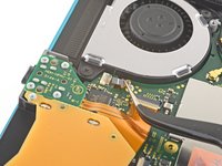
Klappe den kleinen, scharnierartigen Sicherungsbügel am ZIF-Verbinder des Touchscreenkabels mit einem Öffnungswerkzeug oder dem Fingernagel auf.
-
-
-
Schiebe das Touchscreenkabel mit einer Pinzette aus seinem Anschluss auf der Hauptplatine heraus.
-
-
-
Klappe den kleinen, scharnierartigen Sicherungsbügel am ZIF-Verbinder des Kabels zum rechten Joystick mit einem Öffnungswerkzeug oder dem Fingernagel auf.
-
-
-
Schiebe das Kabel zum rechten Joystick mit einer Pinzette aus seinem Anschluss auf der Hauptplatine heraus.
-
-
-
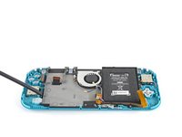
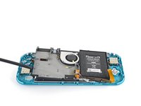
Nimm einen JIS 000 Schraubendreher/Bit oder ein Original PH000 Bit von iFixit und entferne folgende sechs JIS-Schrauben, mit denen die Hauptplatine befestigt ist:
-
Drei 3,1 mm Schrauben
-
Drei 4,5 mm Schrauben
how to get the c port off
When re-assembling, be sure the fan cable (step 25) is completely pulled through prior to tightening the screw that’s right next to it.
-
-
-
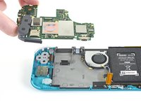
Setze einen Spudger in den Spalt zwischen den Rahmen und der Hauptplatine ein. Hebe dann die Hauptplatine aus ihrer Vertiefung heraus.
-
Entferne die Hauptplatinen-Baugruppe.
-
-
-
Nimm einen JIS 000 Schraubendreher/Bit oder ein Original PH000 Bit von iFixit und entferne die beiden 3,5 mm JIS-Schrauben, mit denen der rechte Joystick befestigt ist.
-
-
-
Entferne den Joystick mit den Fingern.
-
-
In diesem Schritt verwendetes Werkzeug:Tweezers$4.99
-
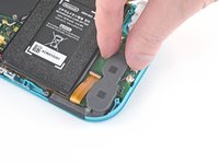
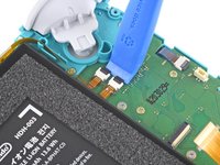
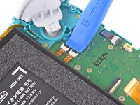
Ziehe den Kabelstecker zum linken Lautsprecher mit einer Pinzette oder deinen Fingern gerade nach oben und löse ihn aus seinem Anschluss auf der Hauptplatine.
pulled from the connector, not the wires, and ended up ripping them off the connector anyways since it encountered tension from the other end (the gray chamber on the left)
consider doing step 15 before pulling the wire, just in case.
Why even disconnect this cable. Not worth the risk leave it connected to daughter board.
while doing this I ripped the pad on the circuit board off. Should i risk trying to repair it or should i just try to go without the speaker???
I also accidentally ripped off the connector, disabling the left speaker. However, that will not break any functionality of the switch. The right speaker works just fine on its own (just remember to turn the audio to mono in system settings) and I was successfully able to replace the joystick. Although the audio quality is a little bit depleted, you barely notice it if you turn up the volume a little, and I think being able to actually MOVE FORWARD in my games is a better plus than having louder, stereo, audio.
Went to pull the speaker connector and it pulled right off the motherboard. Would not come loose.
I'm gonna echo what others said here and suggest that you skip this step. After you complete Step 15, you can just move the speakers enough with your fingers to complete Step 26, which involves a screw half underneath it.
Regarding the ribbon cable in Step 17 & Step 18, you can honestly use your fingers if they're small enough. The ribbon cable is wide enough for you to press down on it a little and slide it out bit by bit.
Overall, this makes the disassembly and eventual reassembly process easier and lets you avoid running the risk of damaging or completely tearing out the wires, like I almost did.Removing the screw from 37 is enough to give you space to remove the board, I honestly think you shouldn't try to remove this connector.
Unfortunately, I had to reinstall multiple daughterboards on the same Switch Lite. I strongly recommend orienting your straight tweezers with ridges (like the ones in the picture) perpendicular to the device. Grab the plastic connector with the tip of the tweezers from the top. It makes inserting and removing this connection significantly easier.
-
-
-
Nimm einen JIS 000 Schraubendreher/Bit oder ein Original PH000 Bit von iFixit und entferne die 4,5 mm JIS-Schraube, die das linke Lautsprechermodul befestigt.
-
-
-
Hebe das Lautsprechermodul mit der Hand aus seiner Vertiefung hoch und entferne es.
-
-
-
Klappe den kleinen, scharnierartigen Sicherungsbügel am ZIF-Verbinder des Verbindungskabels zur Hauptplatine mit einem Öffnungswerkzeug oder dem Fingernagel auf.
-
-
-
Schiebe das Verbindungsabel der Hauptplatine mit einer Pinzette aus seinem Anschluss auf der Tochterplatine heraus.
-
-
-
Klappe die kleinen, scharnierartigen Sicherungsbügel an den ZIF-Verbindern der beiden Kabel mit einem Öffnungswerkzeug oder dem Fingernagel auf.
-
-
-
Schiebe das Displaykabel der Tochterplatine mit einer Pinzette aus seinem Anschluss auf der Hauptplatine heraus.
-
Wiederhole das Ganze für das Flachbandkabel zu den Lautstärketasten.
-
-
-
Entferne die Lautstärketasten mit einer Pinzette oder den Fingern.
-
-
-
Klappe den kleinen, scharnierartigen Sicherungsbügel am ZIF-Verbinder des Kabels zum linken Joystick mit einem Öffnungswerkzeug oder dem Fingernagel auf.
-
-
-
Schiebe das Kabel zum linken Joystick mit einer Pinzette aus seinem Anschluss auf der Tochterplatine heraus.
The connector for my left joystick broke. Is there a way to fix it?
How badly did it broke?
-
-
-
Nimm einen JIS 000 Schraubendreher/Bit oder ein Original PH000 Bit von iFixit und entferne die beiden 4,5 mm JIS-Schrauben, mit denen die Baugruppe der linken Trigger-Taste befestigt ist.
-
-
-
Nimm einen JIS 000 Schraubendreher/Bit oder ein Original PH000 Bit von iFixit und entferne die folgenden vier JIS-Schrauben:
-
Zwei 4,5 mm JIS-Schrauben
-
Zwei 6 mm JIS-Schrauben
The two 4.5 mm screws were very difficult to remove here and ended up getting stripped. I CANNOT remove them, help!
-
-
-
Hebe die Tochterplatine mit den Fingern nach oben aus ihrer Vertiefung heraus.
Stop here if repairing Switch Lite for joycon drift. After removing daughter card you can see the bottom of the joystick. This thin metal actually bends during use causing bad connection of joystick. If you cut out a business card the same size as the joycon and put it on the bottom of the joystick it gives the metal enough backing to fix the issue. I used two layers with just a small bit of glue stick to adhere it. Put it all back together and you will find your issue is fixed.
That's great, but it's only Temporary.
You may as well put a New Stick in (preferably Hall Effect) after going through Hell to open the darn thing.
If you do choose the cardboard route, you may as well clean the innards of the Joystick, BUUUT, it's not easy getting the Joystick back together.
Daughterboard. That's a new one for me.
-
-
-
Nimm einen JIS 000 Schraubendreher/Bit oder ein Original PH000 Bit von iFixit und entferne die beiden 3,5 mm JIS-Schrauben, mit denen der linke Joystick befestigt ist.
-
-
-
Hebe den Joystick mit dem flachen Ende des Spudgers nach oben aus seiner Vertiefung heraus.
-
Entferne den Joystick mit der Hand.
During reassembly when putting the screws back in, slowly turn them CCW until you feel it drop into its thread. You will never crossthread them by doing this.
-
-
-
Nimm einen JIS 000 Schraubendreher/Bit oder ein Original PH000 Bit von iFixit, um die folgenden vier Schrauben zu entfernen:
-
Drei 2,5 mm Schrauben
-
Eine 6 mm Schraube
-
-
-
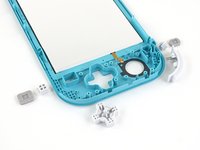
Benutze einen Spudger oder deine Finger, um die Mittelrahmen-Baugruppe aus ihrer Vertiefung zu heben.
-
Entferne die Mittelrahmen-Baugruppe.
-
-
-
Jetzt ist es an der Zeit alle Tasten zu entfernen (sofern noch nicht geschehen), um zu verhindern, dass du welche verlierst.
-
-
-
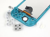
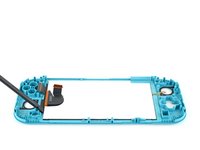
Erwärme einen iOpener und lege ihn 1-2 Minuten auf die obere Kante des LCDs, um den Kleber aufzuweichen.
-
-
-
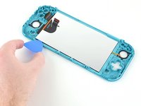
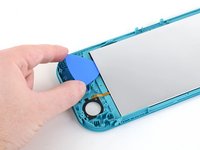
Setze ein Plektrum zwischen den Rahmen und die Oberkante des LCD ein, um die beiden Komponenten voneinander zu lösen.
-
-
-
Schiebe das Plektrum nun entlang der oberen Kante des LCDs, um den Kleber zu durchtrennen.
-
-
-
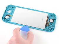
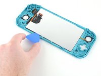
Lege nun zwei Minuten lang den erwärmten iOpener auf die rechte Kante an der Rückseite des LCDs, um den Kleber aufzuweichen.
-
-
-
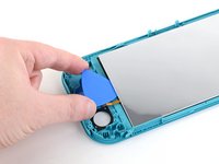
Schiebe das Plektrum weiter an der rechten Kante des LCDs entlang, um den Kleber aufzutrennen.
-
-
-
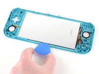
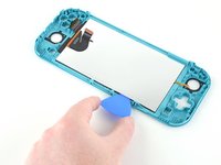
Lege zwei Minuten lang den erwärmten iOpener auf die Unterkante der Rückseite des LCDs.
-
-
-
Führe das Plektrum weiter an der Unterkante des LCDs entlang, um den Kleber aufzutrennen.
-
-
-
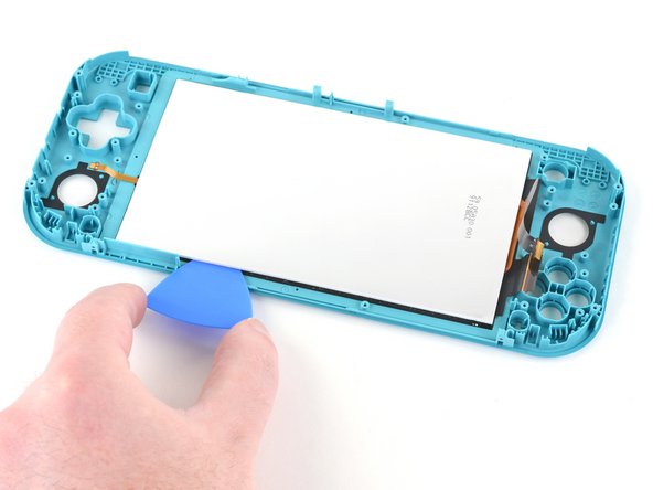
Lege zwei Minuten lang den erwärmten iOpener auf die linke Kante der Rückseite des LCDs.
-
-
-
Schiebe das Plektrum weiter an der linken Kante des LCDs entlang, um den Kleber aufzutrennen.
-
-
-
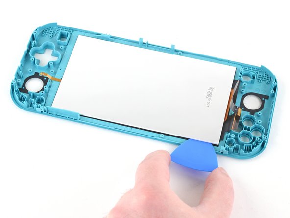
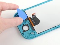
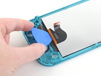
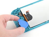
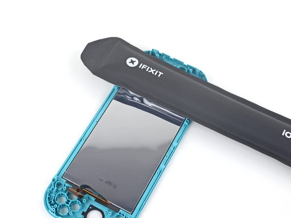
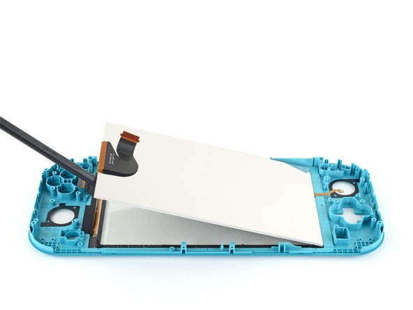
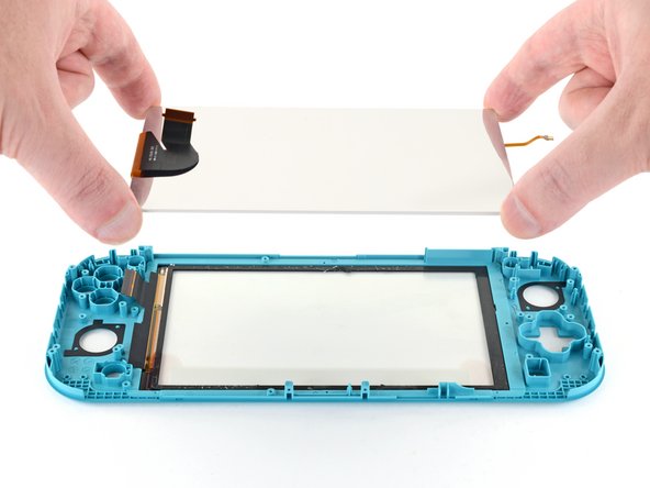
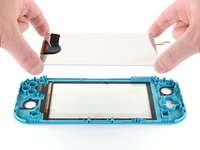
Benutze nun die flache Seite deines Spudgers oder deine Finger, um das LCD nach oben aus dem Rahmen heraus zu heben.
-
-
In diesem Schritt verwendetes Werkzeug:Microfiber Cleaning Cloths$3.99
-
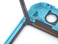
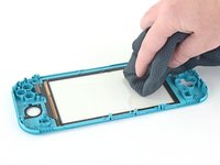
Benutze das flache Ende eines Spudgers, um die Klebereste rund um den Touchscreen herum zu entfernen.
-


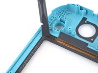
Um dein Gerät wieder zusammenzubauen, folge den Schritten dieser Anleitung in umgekehrter Reihenfolge.
Entsorge deinen Elektromüll fachgerecht.
Lief die Reparatur nicht wie geplant? Versuche es mit einigen grundsätzlichen Lösungsansätzen oder frage in unserem Nintendo Switch Lite Forum nach.
Um dein Gerät wieder zusammenzubauen, folge den Schritten dieser Anleitung in umgekehrter Reihenfolge.
Entsorge deinen Elektromüll fachgerecht.
Lief die Reparatur nicht wie geplant? Versuche es mit einigen grundsätzlichen Lösungsansätzen oder frage in unserem Nintendo Switch Lite Forum nach.
Rückgängig: Ich habe diese Anleitung nicht absolviert.
50 weitere Personen haben diese Anleitung absolviert.
Besonderer Dank geht an diese Übersetzer:innen:
100%


Diese Übersetzer:innen helfen uns, die Welt zu reparieren! Wie kann ich mithelfen?
Hier starten ›

21 Kommentare
Followed the guide to replaced a cracked screen on a Switch Lite, all good, guide was easy to follow and refitting wasn't too hard either, just a reversal of the disassembly
Fantastic guide, exactly what I was looking for! Unfortunately I managed to make the tape unusable and I need tape to connect the lcd to the digitizer and the digitizer to the case. I will likely use 2-3mm tape for the lcd to digitizer but I'm unsure what to use to connect the digitizer to the case. Any suggestions?
Thanks for taking the time to type this up. Really appreciate the effort that went in to this guide.
Great guide, I wish it would mention some of the procedures to tape the screen back in. After that, reversing the process was easy.
For gluing the screen and digitizer back in, I would strongly recommend liquid glue, like Zhanlida T-8000 for example. You can apply it very precisely and you can also correct/remove it if needed pretty easily. I used this stuff to repair around 200 phones and tablets in the last couple of years and were never disappointed.
Also I would remove the digitizer AND the screen together, before removing the screen first from the digitizer… This will make the process of removing the screen from the digitizer a lot easier and safer.
I have ordered a crystal replacement case and a used lite with a scratched digitizer.. Have glued in the replacement digitizer so far, the console should arrive tomorrow.
Gluing in the digitizer was a breeze, just applied some glue all around (be careful not to use too much) and then just pressed down the digitizer all around and put a book on the top… Let the glue harden for around 24 hours and you are good to go.
Will leave some feedback how the screen removal went tomorrow. ;)
Yeah.. The display was actually glued completely together with the digitizer! So not just only on the sides, but on the whole display with an UV reactive transparent glue, like with most smartphones nowadays…
This way this whole tutorial obsolete, because there is almost no way you can remove the digitizer from the display an vise versa…
Also my suggestion was totally right to remove the digitizer and display together.. The way it is shown here is absolutely over complicated.
Maybe the UV glue is used in a new revision ifixit wasn't aware of, but this has to be updated!!!
So I Need to replace Just the glass over the screen but I cant find a replacement or a guide
I just did this repair the other day. You would still need to follow this guide because of the ribbon cable you need to plug in. You just need to take the digitizer off in the end. I would buy an lcd just incase it breaks while trying to get it separated which there is a good chance that will happen.
I was wondering if 99% IPA could be an issue to a screen, I am definitely an amateur at this but originally I was going to replace the joysticks and wanted to clean the console.
In a moment of carelessness I spilled IPA on the midframe assembly and some on the side, which seeped to the screen. I had accidentally doused the screen with a relatively small amount of IPA but I dried off what I could and turned on the screen successfully but there was a light colored splotch on the screen. After a couple of days the splotch on the screen is much smaller but it doesn’t seem like it will go away, is this permanent damage? I am wondering if it is possible to clean or fix this, if I get under the screen is it possible to clean, fix it or do I need a new LCD?
Thank you for any guidance in advance.
What about the outer screen part of the switch lite?
I bought the digitizer and screen all in one from IFIXIT and replaced the screen and now only the backlight comes on and the screen does post battery level or see anything on it other than backlight on. I can hear the buttons work and the touchscreen works. I tried the hold 15 seconds and restart with plugged in and power cable out, it did not work. Does anyone know what may have gone wrong, reseat the cables or do I need a another new screen?
Excellent guide simple to follow and in the end an easy repair. Thank you
please don't follow this guide. I should've read the comments before attempting anything. Heat the front instead and remove the whole assembly. Couldn't get properly in between with the pick to slice the adhesive so the lcd cracked..
Followed this guide and worked for me despite the difficulty in separating the digitizer from the LCD. I wonder how this can be avoided in the first place - my kids have 2 switch lites and both had the exact same LCD problem.
I’ve been given a Switch Lite that powers on but there is no display. It sounds like all the controls and touch screen are working fine but there is clear signs of drop damage on the rear casing.
I have reseated the ribbon cable in step 27 but there is not the lower ribbon cable in step 42. It just isn’t there or underneath the daughterboard. What is this ribbon for?
I have discovered that the backlight is not working as I can see the OS if I shine a torch on the screen.
Any thoughts?
Found the backlight ribbon cable sandwiched between the glass and plastic casing!
Fully working!!!
Merci! Je n'avais jamais cait ce genre de truc avant et en suivant les étapes, j'ai réussi à réparer la switch de mon garçon. 😊 Ce guide est super bien fait, j'adore
I swapped out the thumbsticks in a Switch Lite, yet it will not power on now. I'm thinking I used metal tweezers which shorted it out. How can I remedy this?
Tip, flip the switch over when doing the last few steps with the picks, LCD has two parts and it could be difficult to see if it is getting under the adhesive. Ended up destroying my LCD this way, as it wasn't completely under it.
All my screws got stripped any ideas on how to remove?
Almost A Mammal - Antwort
A Y0 screwdriver seemed to work better for me.
Tommy Morrill - Antwort
What type of screw driver do I use to un screw the screws and which way
Luca Capito - Antwort
Y 0.6 was all I had but it seemed to fit perfectly
Trevor - Antwort
Like really snug? I've gotten away with using Drivers either bigger or smaller but I hate doing it. But if 0.6 is the exact size I need, then I'll get that. I don't wanna strip my client's Switch Lite's screws.
Vincent Valodze -