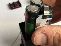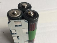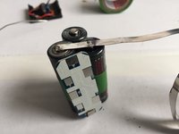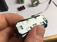
Rollei 6000/6008 LiFePO4 Batterie tauschen
Einleitung
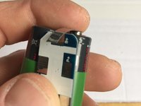
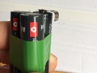
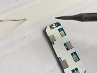
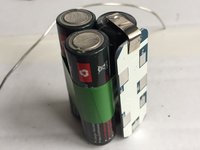
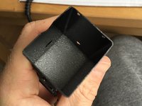
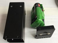
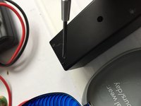
Zu Schritt 1 der AnleitungErsetze die defekte Rollei Originalbatterie durch eine moderne LiFePO4 Zelle.
Hinweis: Die Batteriespannung eines voll aufgeladenen LiFePO4-Akkus fällt leicht ab, wenn die Kamera Strom verbraucht. Das führt dazu, dass die Kamera ziemlich schnell einen fast leeren Akku anzeigt (zumindest bei meiner 6008AF ist das so).
Darüber braucht man sich keine großen Sorgen machen, denn LIFePO4-Akkus halten das Spannungsniveau problemlos über einen längeren Zeitraum.
Was du brauchst
Ersatzteile
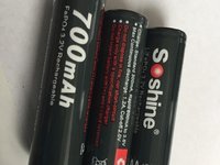
- 14500 LiFePO4 Battery (Soshine N4 700mAh LiFePO4)Erhältlich bei Amazonhigh constant power output (I had success with batteries having a continuous discharge:10C and pulse: 20C)Anzeigen
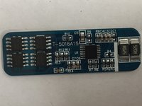
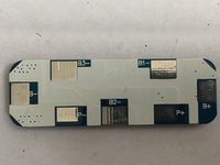
- 8A 9.6V PCB BMS Protection Board for 3 Packs 18650 LiFePO4 LiFe Battery Cell 3S (T‑5016A15)Erhältlich bei AmazonI picked the one with highest current I could find, since the Rollei has a high draw if switched on.Anzeigen
- Anzeigen
- Anzeigen
- Anzeigen
Werkzeuge
Mehr anzeigen …
Einführungsvideo
-
-
Pass auf, dass du die Schrauben nicht verlierst. Sie gehen schnell verloren und sind schwierig zu ersetzen.
-
Pass auf die Kabel auf. Diese sind ziemlich kurz.
-
-
-
Abhängig vom verbauten Akkutyp kann das gegebenenfalls etwas anders aussehen.
-
Manchmal sitzen die Akkus ziemlich stramm. Hier kann es helfen, vorsichtig mit einer Zange zu ziehen.
-
-
-
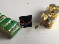
Die originalen NiCd-Zellen hatten zwei zusätzliche Kabel für einen Temperatursensor. Man sieht das auch bei dem gelben Pack, welches ebenfalls das originale Plastikgehäuse hat.
-
Bitte stelle sicher, dass der alte Akku ordnungsgemäß entsorgt wird! Die Zellen enthalten schädliche Chemikalien!
-
-
-
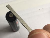
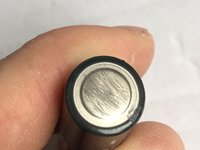
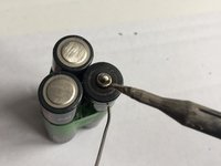
Durch das Aufrauen der Oberflächen wird das Löten erheblich erleichtert.
-
-
-
Ich musste im Nachhinein eine der Batterien umdrehen, um das Löten zu erleichtern... hängt allerdings von der Verkabelung ab.
-
-
-
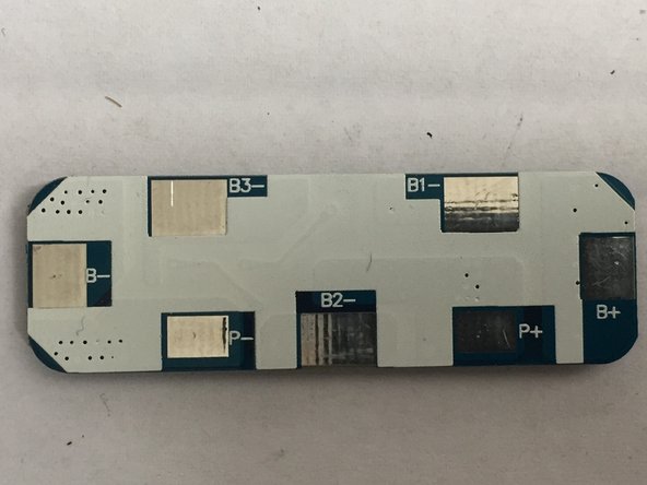
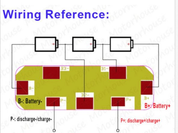
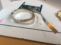
Die PCB/BMS-Platine und der Schaltplan
-
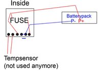
Der Schaltplan kann je nach verwendeter PCB-Platine eventuell abweichen, aber das Prinzip ist für alle Versionen identisch.
-
-
-
Kontrolliere die Größe des Akkupacks zusammen mit dem BMS. Es soll problemlos mit etwas Luft in das Gehäuse passen. Falls nicht, wird das am Schluss zu Problemen führen, wie du am Ende der Anleitung sehen wirst.
-
-
-
Hier kannst du normalen, dünnen Draht verwenden. Beachte jedoch, dass der Platz im Gehäuse begrenzt ist.
-
-
-
Das ist abhängig vom verwendeten PCB und unterscheidet sich von Fall zu Fall.
-
-
-
Gebe etwas Lötzinn auf die Stelle, die du als nächstes löten möchtest. Ich hab damit begonnen, den B+ Anschluss an den Pluspol der Zelle zu löten.
-
Überprüfe erneut, ob noch alles ins Gehäuse passt.
-
ACHTUNG! Das Gehäuse besteht aus Metall! Pass auf, dass Du keinen Kurzschluss fabrizierst!
-
-
-
-
Nochmal die Warnung: Fabriziere keine Kurzschlüsse!
-
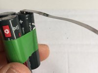
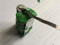
Die Verwendung des Nickelstreifens spart viel Platz im Gegensatz zu Drähten.
-
-
-
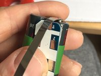
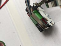
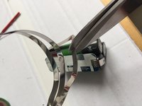
Falte den Blechstreifen und drücke ihn mit der Zange flach.
-
Mit der Schere kannst du die Länge zuschneiden.
-
Versehe den Nickelstreifen wieder mit etwas Lötzinn.
-
-
-
Fertige Lötung aus Schritt 12
-
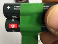
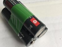
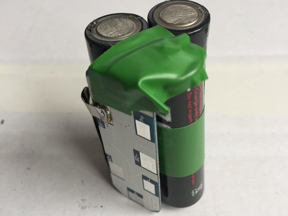
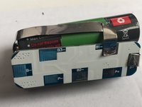
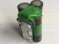
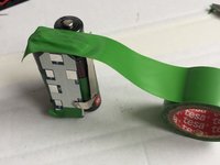
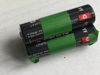
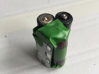
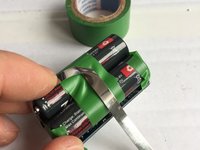
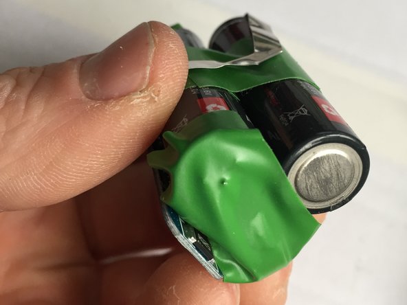
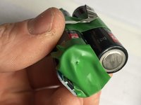
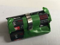
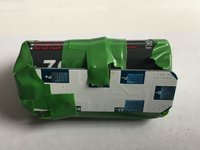
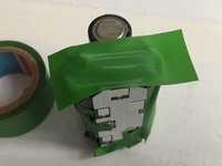
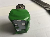
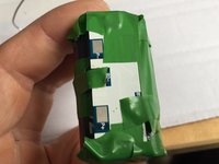
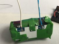
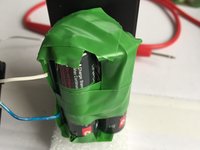
Verwende Isolierband, um das Akkupack entsprechend zu isolieren, um Kurzschlüsse zu vermeiden!
-
-
-
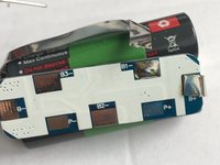
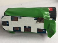
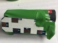
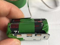
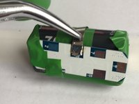
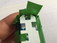
Versuche so zu isolieren, dass die Beschriftungen auf der Platine weiterhin lesbar sind. So erkennst du, was bereits verbunden ist.
-
-
-
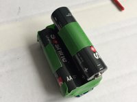
Es ist schwierig, die Orientierung zu behalten, wenn alle Batterien beim ersten Versuch korrekt sitzen. Das Klebeband ermöglicht jedoch bei Bedarf ein Zuschneiden und Neuausrichten.
-
Dies kann hilfreich sein, um möglichst wenig Verbindungen und eine einfache Verkabelung ohne Kreuzungen zu erreichen.
-
-
-
Gebe wieder etwas Lötzinn auf die Pole.
-
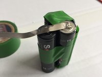
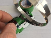
Falte den Verbindungsstreifen
-
Pass auf, dass du nichts kurzschließt!
-
-
-
Nun erkennst du, warum das Isolierband so wichtig ist. Wenn der Verbinder die falschen Stellen berührt, kann es zu einem Kurzschluss kommen, welcher die Platine beschädigen kann.
-
-
-
Die Zange verhindert, dass du dir die Finger verbrennst.
-
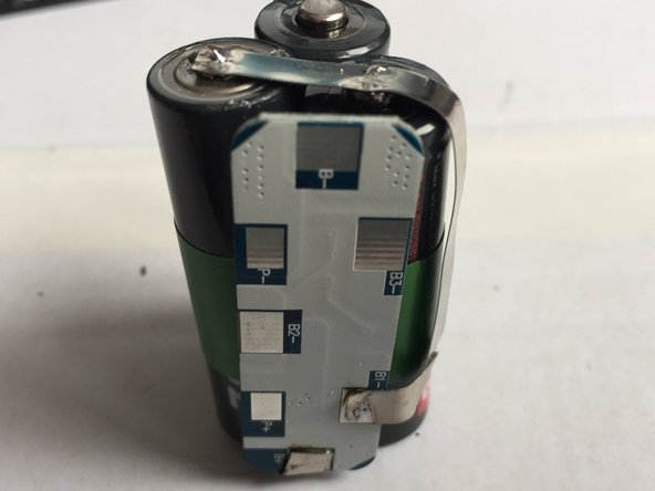
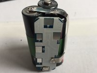
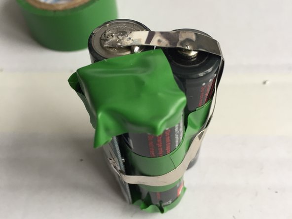
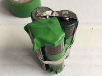
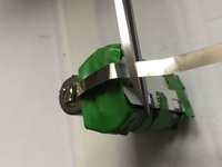
Auf Bild 2 ist gut zu erkennen, wie viel Platz durch die Verwendung des Verbinderstreifens eingespart wurde.
-
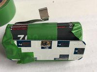
Auf dem dritten Bild ist erkennbar, wie das Lot das Isolierband durchbohrt hat. Im nächsten Schritt machen wir zur Sicherheit noch eine weitere Lage dazu.
-
-
-
Ich schneide das Isolierband im Bereich der Markierungen auf der Platine aus.
-
-
-
An den Kreuzungspunkten fügen wir noch eine weitere Lage Isolierband hinzu.
-
-
-
Beachte, dass im Schaltplan der B3 - Anschluss nicht belegt ist.
-
Darum isolieren wir diesen entsprechend.
-
-
-
Das sind die Lade-/Entladeanschlüsse des Akkupacks.
-
Stelle sicher, dass die Kabel lang genug sind, um sie später an der Rollei anschließen zu können.
-
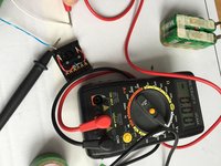
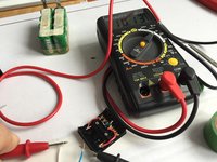
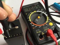
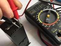
Wenn du mit dem Multimeter misst, wirst du feststellen, dass die Spannung 0V beträgt.
-
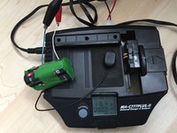
Die Platine muss erst aktiviert werden. Das wird durch ein kurzes Aufladen erreicht.
-
-
-
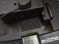
Ein kurzes Aufladen reicht aus und das Ladegerät zeigt eine Spannung von 10,4V an.
-
Nun zeigt auch das Multimeter die korrekte Spannung an.
-
Das PCB ist nun aktiviert und das Akkupack korrekt verdrahtet.
-
Wenn dieser Schritt NICHT wie erwartet FUNKTIONIERT, überprüfe nochmals alle Lötungen und Verbindungen, um sicher zu gehen, dass keine Fehler vorliegen.
-
-
-
Dies ist der schwierigste Teil der Löterei.
-
Vergewissere dich, dass nichts angeschlossen ist, was nicht angeschlossen sein sollte.
-
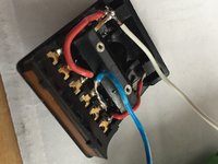
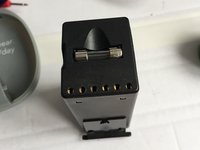
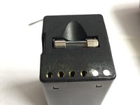
Die Batterie hat zwei "+" und zwei "-" Pole. Stelle sicher, dass "+" (das weiße Kabel) mit dem richtigen Eingang verbunden ist. Kontrolliere die roten Kabel - eines geht direkt zum Kameraanschluss, das andere ist durch eine Sicherung geschützt, welche die Kamera schützt.
-
-
-
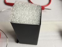
Probiere aus, wie viel Schaumstoff benötigt wird.
-
Lasse oben genügend Platz für Kabel und Sicherungen.
-
-
-
Richte Akkupack, Deckel und Gehäuse aus.
-
Beachte, dass sich die Schrauben nur auf einer Seite befinden.
-
Auf der anderen Seite rasten zwei kleine, quadratische Rasten ein.
-
Überprüfe, ob sich der Deckel vollständig und ohne großen Druck schließen lässt (Bild 3). Entferne sonst etwas Schaumstoff.
-
-
-
Hinweis: Der Deckel ist jetzt umgedreht (also spiegelbildlich zum Schaltplan)
-
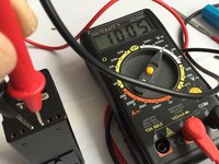
An den beiden rechten Anschlüssen erwarten wir eine gemessene Spannung von 0V.
-
Vergewissere dich, dass bei richtiger Polung ungefähr 10V gemessen werden.
-
Wiederhole diese Messungen nochmals, um absolut sicher zu sein, dass wirklich alles korrekt ist, BEVOR du den Akku in die Kamera einlegst!
-
-
-
Fülle die beiden unbenutzten Anschlüsse (vom Temperatursensor) mit Kleber. Dadurch wird verhindert, dass versehentlich ein Rollei-Ladegerät N oder G verwendet wird, das nicht für den Akkutyp geeignet ist und einen Brand oder eine Explosion verursachen kann.
-
Lade den Akku nur mit einem passenden LiFePO4-Ladegerät auf!
-
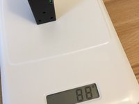
Beachte, dass der Akku nun nur noch 81 Gramm wiegt, im Gegensatz zu den 210 Gramm des alten NiCd-Akkus.
-
Viel Spaß bei der weiteren Nutzung deiner Rollei!
-
-
-
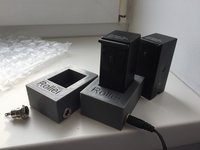
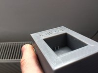
Im Anhang findest du eine STL-Datei (unter „Medien“) zum 3D-DRUCKEN einer Ladeschale für das neue Pin-Layout (denk daran, einige Pins zu blockieren, damit der Rollei Charger N Deinen neuen Akku nicht beschädigen kann). Das 3D-Modell kann auch hier heruntergeladen werden: https://www.thingiverse.com/thing:215677...
-
Drucke das 3D-Model aus (oder lasse es von einem Druckdienstleister erledigen)
-
Besorge dir eine passende Anschlussbuchse mit 12,6 mm Durchmesser (es geht auch eine andere, aber dann muss eventuell das 3D-Modell angepasst werden).
-
Löte Kabel an die Pins (überprüfe, dass die Maße der Pins zum Akku passen!). Vergewissere dich, dass sie stark genug sind, um elektrischen Kontakt herzustellen. Ich hab zwei kleine Nägel verwendet, die ich gekürzt habe. Klebe die Stifte so in die Bohrungen des Gehäuses, dass sie 5-6 mm herausstehen. Teste, ob der Akku gut kontaktiert ist.
-
Löte die andern Enden der Kabel an die Buches und klebe diese in das dafür vorgesehene Loch. Befülle die Unterseite mit Heißkleber, um alles zu fixieren.
-
Ein Ladegerät kann bei eBay bestellt werden: Suche nach "11V Charger 1A Smart to 9,6V LiFe LiFePO4"
Hi,
I'm just waiting for all the parts to arrive, just checking on the pins attached to the 3D cradle, looking from the top, and the word Rollie, is the + pin, the one on the left ie nearest to "R". And to activate the PCB can we just just use the recommended 11V charger in the link?
Yes that should be right. See drawing on Step 24. It's upside down in the charger case. https://guide-images.cdn.ifixit.com/igi/...
-
Nun macht die Rollei wieder richtig Spaß! :)
Nun macht die Rollei wieder richtig Spaß! :)
Rückgängig: Ich habe diese Anleitung nicht absolviert.
4 weitere Personen haben diese Anleitung absolviert.
Besonderer Dank geht an diese Übersetzer:innen:
100%
Diese Übersetzer:innen helfen uns, die Welt zu reparieren! Wie kann ich mithelfen?
Hier starten ›
43 Kommentare
Hello Markus,
I have followed your instructions to rebuilt the battery pack. Batteries charged as expected to 10.4V, however both of my cameras 6008I and 6008 AF showing “Charge” briefly and will not turn on with the new LiFePo4 pack. I think the selected voltage of 9.6V is probably just too low.
Thanks,
Victor Dombrovskiy
Hello Victor,
It looks like we have the same issue with our 6008 AF. Mine does not work correctly. It turns on, it meters exposure but neither AF no rewind mechanism work. I am arrfaid the reason is not voltage only, there should be other reason.
Kind regards,
Hermann
Hi,++Markus++ ,
What charger is used to charge the battery?
I am using one of these: P2012-l3 12.6v 1.5a LiPo Lithium Ion Charger for 11.1V Li-ion Battery
The PCB BMS Protection Board for 3 Packs 18650 LiFePO4 LiFe Battery Cell 3S does the balancing and cut off. So every “C.V. Voltage for LiFePo4: 10.8V±1%” should work.
Hi,Markus,
That link had been failed.I want to ask is you list charge is a DC mount, how to contact with battery ? battery has six holes.If you provide a photo when charging battery is very good.
The battery has 6 holes. 2 are unused (temperature sensor needed only for original charger). Thats the ones closed so the converted battery cannot end up in a Rollei Charger that might fry/burn them. The other 4 pins are both battery out. Fused and unfused. The fused are needed to not break the motor of the camera if the film is stuck in the magazine. So for charging both pairs are be fine (as long as the charging current is lower than the 1A of the fuse). I used the two center pins (unfused) in the 3D printed case.
Markus -
This is my charging tray: https://www.thingiverse.com/thing:215677...
and again a link for the exact charger I use: https://www.ebay.com/itm/P2012-l3-12-6v-...
The 3.7V batteries would be LiIon not LiFePO4. the LiFePO4 have 3.33V which adds up to the 10V. 3.7V * 3 sums up to 11.1V. Which I didn’t want to try back then (risk of damaging the camera with over voltage). But there is now a company offering LiPo battery replacements (see here for picture: https://www.photoscala.de/2017/10/05/neu...).
SO to sum it up, the 11.1V doesn’t seem to be a problem for the cameras. To do so, you will need another BMS Board (for 3S LiPO/LiIon) though to have another cutoff voltage.
I’ve had a lot of trouble with batteries, and had multiple versions of rebuilds. The LiPo rebuilds won’t work with the 6008AF. I don’t think this will reliably work either. PLUS. You’re bypassing the temp sensor. That means you risk frying your main board on the camera. Impossible to buy. The batteries that have been converted previously to LiPo have the sensor removed, meaning they can’t be rebuilt properly. So the supply of good shells is dwindling. I have two fully empty shells that were sold to me as fully functioning. Not.
Essentially, the guys who really know these cameras are suggesting NiMH Only, especially for the 6008AF.
The temperature sensor isn’t even used by the camera. Take a look into the slot of the camera with the battery removed. There are just 4 pins. The original Rollei charger has 6 pins and uses the temperature sensor. There are aftermarket chargers (e.g. MaHa) that have a magnetic temperature sensor to not fry the battery. The problems you might have seen is the high current draw peak of the linear aperture motors (up to 4.5A)!
Markus -
Well I also had lots of troubles with batteries. The NiMH variants (self build and ready made pick from China) both had too low voltage for my 6008AF. (I was using the MaHa charger to charge). Then I had many trails with LiIon and Voltage converters (1 and 3 cells). The LiFe setup as described above works for me. The camera is fully functional on a battery that has been charged 6 months ago (don’t have PQS lenses though). Your comment on the thermal sensor and motherboard frying is completely wrong. The sensor is to prevent overheating while charging. What you’re referring to is the fuse. Just look inside the battery compartment of the camera the thermal sensor isn’t even connected.
Please I’m making the battery with the Soshine 3.2V 700mAh AA /14500 LiFePO4. But I have Charger N for my Roolei old batteries and where i can found now a charger for the new batteries. Because i don’t want to reopen everytime to charge. In the pictures i see a charger but i don’ tfind in Ebay. Please write me one. Thanks
Hi Carlos,
You basically need an CCCV charger for LiFe. If you got the BMC built in it it will handle the balancing of the three cells and cut off if charged.
Basically the search term is LiFePo4 charger 3S (3 cells) e.g. something like that: https://m.aliexpress.com/item/3281134765...
I also created a 3D Model for a charger stand (to be 3D printed) . If you like I have a spare set (unused that I would sell) . Otherwise the model is available here: https://www.thingiverse.com/thing:215677...
Currently this link can be used to order a charger: https://www.ebay.com/itm/11V-Charger-1A-...
What did you use for the metal pins in your charger base? I’m having some trouble finding suitable ones to make a connector for the battery charger.
The pins (to solder on somewhere) that are readily available all are either to thin (1mm) or too thick. So I ended up using two small nails I had available with 1,5mm diameter. Just make sure to shorted with pliers. Also used some sanding paper to get rid of the rust proving surface to make sure there is electric conductivity. When gluing in the „pins“ I made sure they have a slight angle on a few degrees so it actually „locks“ the battery slightly .
Markus -
Thanks for the info on the pins Markus. I was able to complete the battery with 3 600mAh LiFePO4 2C cells, however my 6008 just says “Charge” when trying to use the pack. I thought that may be due to the 2C discharge rate being too low, but I tried this battery LiPO upgrade in this method: https://www.photrio.com/forum/threads/th... and still only got a “Charge” message from my camera. What I’m wondering now is if there’s just something wrong with my camera in how it is checking battery power, but that’s beyond my current electronics ability to know what to look for. I did notice that even with my NiMH packs it says “Charge” as soon as they fall from peak voltage off the charger down to their nominal output.
Hi Justin,
sorry to hear that. I just have a 6008AF which shows a half full battery with the 10V of my pack. It stays in a functional state for months without recharge and I am able to use the camera for many roles of film. I was initially trying to get this done with LiIon batteries and step-down bucket converter, but those didn’t deliver the needed current for the camera. It’s the linear motors of the shutter that has high initial drain. You can check if the current is too high by powering the camera without a lens attached. If it works then the maximum current delivered by the pack is not sufficient. Otherwise your camera wants to have a higher voltage. I was scared to fry the camera if i use much higher voltage. 3x3,7V of LiIon for example. But meanwhile I know Wiesner Phototechnik created a 11,1V pack so I guess it would have been ok. But after charging the LiIons tend to have 4,1-4,2V which would be 12,6V not sure if s.o. here know this would be too much.
Markus -
Sorry its Phototechnik Wiese: https://www.photoscala.de/2017/10/05/neu...
They also use LiPo 11,1V packs like those you (?) linked above. I was also looking into that, but didn’t find a pack that would fit into the original case.
I had the issues you have with the camera showing “Charge” with a premanufactured NiMh pack I purchased from eBay, wich just had 9,6V. The cameras seem to be very picky on the voltage.
Also the high initial drain creates a voltage drop on many batteries. I tried to measure the current once, but the tools I had supported max. 2A and those I got.
Also check what the battery management board you use can handle as max current. That could also be the bottleneck. Or the type of wiring inside the battery. Thats why I used those flat connectors.
Thanks Markus, you’re right they do seem to be extremely picky on the voltages they’ll work with. I think there may just be something wrong with my current 6008 due to what I described earlier. My brother shipped me his 6008 to try and it worked perfectly with the 9.6v and 11.1v packs. It even seems to last long using the NiMH packs I was trying in mine. I guess I may need to pack up my body and ship it out to Paepke Fototechnik for a checkup and possible repair.
Justin -
Hi! Thank you for an awesome manual! I’m just about to make this build, and I’m waiting for all the parts. I just wonder if I can use this charger that I already own, will the PCB regulate this? It’s an 12.6v 1,6A. Or do I need to buy the 11v -1A that you linked?
All the best,
Simon
Hi Simon, depends on the max Voltage specs for the BMS. Check the max. input voltage in the datasheet. I would assume it to be fine but make sure to check before so you don’t fry the BMS.
Markus -
Just checked: Charging voltageDC:11V CC/CV so you need an 11V CC/CV charger for it (at least from what I can see from the data sheet).
Markus -
Thank you so much Markus! I’ll get the 11v charger then to be safe!
Hi again Markus! Just wondering, is the BMS only regulating the charging part? If I went the route of charging the individual cells outside in a normal charger for LiFePO4 batteries with a BMS built in, would I still need the BMS? Otherwise I could just use a standard AA-cradle so you can easily take them in and out once you screw the pack open.
The BMS is doing the balancing of the pack. If you don’t have one you’ll have to charge each cell
individually to not fry one while trying to get the others to the same charge level. You’ll have to get the cells out of the Rollei battery case each time nothing I would recommend. It’s rather tight in there.
I know some guys have built replacements with LiPo packs. Look for Turnigy nano-tech 11.1V packs. EFLB4503SJ30 or https://www.amazon.com/Turnigy-Nano-tech... but the second one is supposed to be very tight. Be sure to check the size before. Also you have to get the balancer connector accessible some how. But that would be less soldering.
Markus -
Which terminals should I be charging the battery with?
Will a multi charger be OK?
I used the two center pins because the + wire by-passes the fuse then. Whats a multi charger? The BMS module just needs the correct voltage. If you have exactly the same BMS then take any 11V CC/CV charger like shown above (or any that works within specs of the BMS module).
Markus -
Thanks for your reply.
The battery pack I have has been re-packed with 8 No. 1.2v NiMh batteries.
So 9.6 volts.
Will this be enough to run the camera?
I have a charger now so I can charge the pack up & see what happens!
I have a camera & 3 lenses & just wanted to test it all before I sold it for the son in law.
Ended up costing me about £200.00 so far!
it works. shutter speeds etc etc. lenses all ok apart from 1 which has a displaced aperture blade.
But.
always shows under exposed in the display?
is this an easy fix?
For Step 30 - can you add pictures of the bottom of your charging tray where you've soldered the pins to the charging terminal? I've just 3D printed out the frame and got all the parts together, but I'm unsure how to connect the charger wiring.
Hi Cameron, dang I don’t have a picture from below before being having the glued.
but I can describe a bit mor in detail. Take two nails and test them to get the proper length and diameter. Then take the wires and loop them just above the nail head (with the tip of the nail pointing up). Then solder it there (the head of the nail will prevent it slipping off. Then test the length by putting the nails from the bottom into the holes of the battery socket. The soldered cables should be just at the underside if the holes. If everting is fine, put the cable true the jack hole (inside out). Solder it correctly to the jack. Test polarity and then glue or press the jack hole. Put the cable inside and file the hole from the bottom with hot glue or similar.
Markus -
Thank you Markus - I'll give that a shot. I successfully built the battery and charged it manually with a power station for the time being. I put it back in the body I got at a photo auction and it works (mostly)!
Shutter speeds, mirror function, and remote trigger all seem to work. However, the data readout is inverted (almost as if the camera is expecting the prism finder to flip the information left to right). Waist level finder is backwards but prism finder properly flips the readout to the appropriate order. Any ideas as to how to switch this? Might be old electronics that are fried too. Not a deal breaker for me.
Hi , I built this based on your direction but when I charge after while I still get zero volt when I disconnect from the charger
what can be the problem?
The BMS might be in blocking mode. Check the technical specs, you might need to set a voltage to a set of pins to activate it. usually this is done with a full charge, but might be dependent on the BMS specs. Other options… it might be just faulty or broken due to excessive heat while soldering. Take a look here: https://electronics.stackexchange.com/qu...
Markus -
Thanks Markus for making this, I have SLX camera and I made the battery pack based on your direction, and charged it I get 9.6V from battery, but when I put the battery the camera doesnt work and battery goes back to 0 volt
any idea what is wrong with it?
note: the camera was working with the original batteries but wanted to renew batteries so there is no problem with camera


