
Leistungseinstellung der Laserlinse
Einleitung
Zu Schritt 1 der AnleitungDiese Anleitung zeigt, was zu tun ist, damit deine Spiele-CDs wieder richtig gelesen werden.
Wichtig: die Schritte 11 - 16 sind nicht unbedingt nötig. Du kannst einfach von Schritt 10 nach 17 springen.
Was du brauchst
Werkzeuge


Mehr anzeigen …
-
-
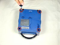
Drehe den GameCube um, so dass die Unterseite des Gerätes nach oben zeigt.
-
Entferne alle vier Schrauben mit einem 4,5 mm Gamebit Schraubendreher.
-
-
-
Wenn alle vier Schrauben entfernt wurden - das Gerät liegt weiterhin mit der Unterseite nach oben - kann man das Geräteunterteil vorsichtig nach oben ziehen und vom oberen Gehäuseteil trennen. Das Unterteil wird nun mit dem Bauteilinneren nach oben auf einer Unterlage abgelegt.
-
Lege das Unterteil mit der Innenseite nach oben.
This can also be done whilst being in the normal upright position after all 4 of the 4.5mm Gamebit screws have been removed. Pull the top of the shell directly upwards and it should slide off easily.
Less chance of snagging any wires or parts.
-
-
-
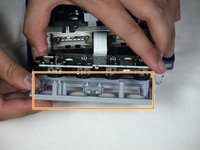
Drücke leicht auf die Klammern an den Seiten der Gehäuserückwand.
-
Entferne die Rückwand vorsichtig vom Gehäuse des GameCube.
A second picture clearly showing which direction to pull the back panel away from the unit would be nice.
-
-
-
Bei abgenommener Rückwand können nun vorsichtig die Controller-Ports auf der Vorderseite des Geräts abgesteckt werden.
well... what happens if accidentally i disconnected it?
presumably nothing major. The CMOS battery is attached to the controller ports, so the most i'd expect is that the gamecube loses it's date/time setting. As long as you reset that before jumping into animal crossing or something, you should be fine. I'm currently doing a teardown of my gamecube, and if something does prove to have gone wrong, i'll report back.
sigoshi -
okay, i finished putting it back together. gamecube works fine and surprisingly still remembers what year it is. boots into smash bros and shows memory card contents fine.
sigoshi -
-
-
-
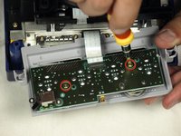
Entferne die zwei PH2-Kreuzschlitzschrauben auf der Rückseite des Steueranschlusses.
-
Trenne nun vorsichtig die graue Gehäuseverkleidung des Steueranschlusses von der Platine ab.
must do this?
That step is not needed for the laser replacement.
Love ur labeling and legends. Good on ya
Not a necessary step
-
-
-
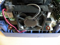
Auf der linken Seite der Einheit befindet sich der Lüfter inkl. Gehäuse.
-
Entferne nun vorsichtig die zwei Schrauben, die das Lüftergehäuse mit der Einheit verbinden.
Why can't the fan wire be detached?
It can, but you might not want to
-
-
-
Entferne die vier Kreuzschlitzschrauben #1, mit denen die Erdungsfedern befestigt sind.
-
Nimm nun vorsichtig die Erdungsfedern heraus.
-
-
-
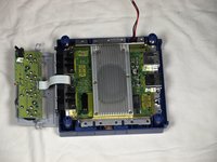
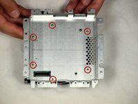
Das optische Laufwerk ist auf einer Metallplatte befestigt.
-
Entferne nun die zwölf Schrauben, die rund um das optische Laufwerk angebracht sind.
Are these 12 screws the exact same kind like the 2 that were on the fan?
Yes! As far as I can tell anyway. Makes sense, too since opposite the fan you have five of the same holes as well.
-
-
-
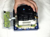
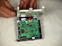
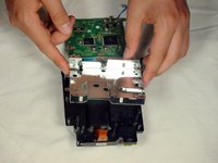
Trenne nun vorsichtig die Laufwerks-Baugruppe von der GameCube Einheit.
-
Die Laufwerks-Baugruppe ist durch eine Nut an der darunterliegenden Hauptplatine befestigt. Möglicherweise braucht man etwas Kraft, um die Baugruppe vorsichtig zu lösen.
-
Die Metallplatte und das eigentliche optische Laufwerk bleiben miteinander verbunden.
-
-
-
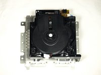
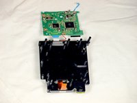
Jetzt sollte das optische Laufwerk vom GameCube getrennt sein.
-
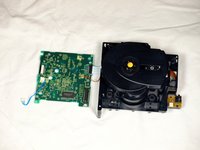
Drehe das optische Laufwerk mit der Unterseite nach oben.
-
Entferne die sechs Kreuzschlitzschrauben #1.
-
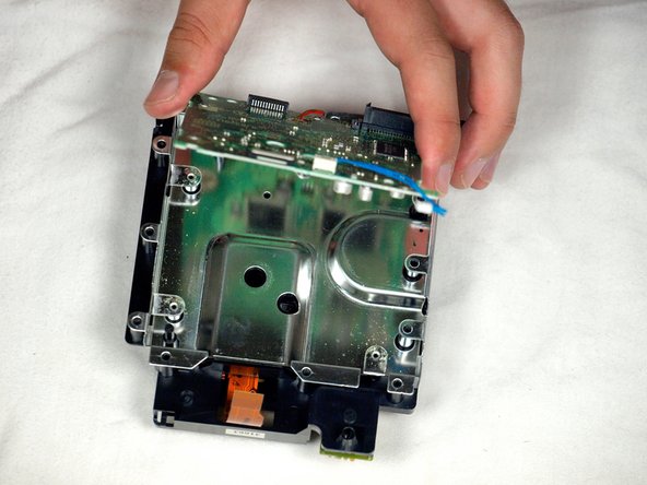
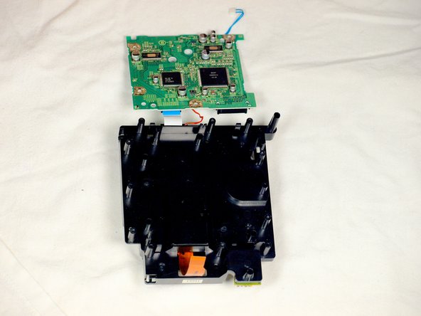
Hebe die Metallplatte vorsichtig an und entferne sie.
If you are just doing the lens power adjustment, from this step skip straight to step 17. Steps 11-16 are unnecessary unless you are replacing the lens completely.
-
-
-
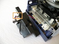
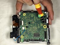
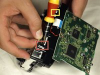
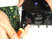
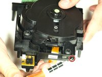
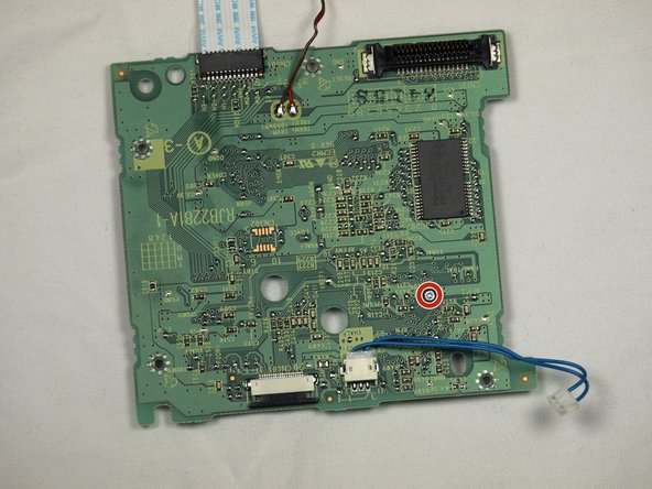
Entferne das blaue Kabel durch vorsichtiges Ziehen.
-
Trenne das braune Kabel ab. Ziehe dazu vorsichtig die schwarze Lasche vom weißen Kunststoff ab. Dadurch wird das braune Kabel gelockert, so dass es vorsichtig von der Lasche weggeschoben werden kann.
-
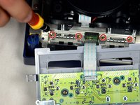
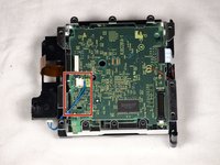
Entferne die vier Kreuzschlitzschrauben #1, die die Leiterplatte mit der optischen Laufwerksbaugruppe verbinden.
-
Die vierte Schraube befindet sich hinter dem Schraubendreher in der dritten Abbildung.
A helpful addition/change to this step would be to include a photo of where/how to remove the brown ribbon cable (maybe also include this terminology in the text, instead of just “cable”). Furthermore, the yellow box to indicate the blue cable highlights everything except the part that you need to remove, which is a little confusing.
Thanks!
Ben
I cannot get the 4 little screws to go back into the board once removed. There is nothing for them to bite into - how do I get this board put back together?
I had this same issue — until I realized that the metal plate goes back on BEFORE the circuit board XD. Once you out the metal plate back on and put the circuit board on top of that, the screws should go in okay.
-
-
-
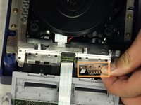
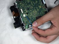
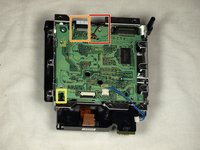
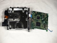
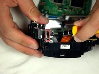
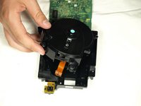
Löse die kleine Raste, mit der die Leiterplatte befestigt ist.
-
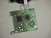
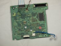
Entferne vorsichtig die Leiterplatte (das große grüne Quadrat), wie in den drei Abbildungen gezeigt.
-
Rotes Kabel
-
Weißes Flachbandkabel
What would happen if I accidentally separated the white ribbon cable... because I watched a video of some guy going through this same process. Separated all the cables and his worked. My cube stopped reading disks recently. Laser is calibrated properly. Begins to spin then stops
Ps
Is there anyway I can save my cube
I'm just guessing here, but I think they mean there's no need to separate those cables to complete the repair—just be careful not to pull or stress them. Like you said, nothing bad will happen if you choose to disconnect a couple cables. As for what's wrong with your cube, you might want to try asking your question over in the Answers forum.
There is a small tab to the left of the red wire that you need to pull out to release the circuit board.
Why do we need further disassembly that this ? The potentiometer is already accessible at this point. Why do we need to tear down the lens from it’s slot in step 16 ?
Good question! I’m wondering the same thing.
You don’t. You can stop here if you’re doing the laser potentiometer calibration.
jweeman -
-
-
-
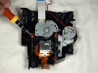
Löse mit einem Schlitzschraubendreher vorsichtig die vier Kunststoffklammern, mit denen die Laufwerksbaugruppe zusammengehalten wird.
Since this step uses a flathead screwdriver, it might be useful to include that in the list of required tools at the top.
-
-
-
Hebe die Metallplatte vorsichtig von der Laufwerksbaugruppe ab.
-
Drehe dann die beiden Hälften der Laufwerksbaugruppe um.
-
-
-
Löse mit einem Schlitzschraubendreher die beiden Clips an der hinteren Hälfte der Laufwerksbaugruppe.
-
Der letzte Clip braucht nicht gelöst zu werden; die obere Hälfte der Laufwerksbaugruppe gleitet von der unteren Hälfte weg.
-
Nimm die obere Hälfte der Laufwerksbaugruppe aus der Basis heraus.
-
-
-
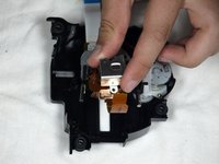
Sobald die obere Hälfte der Laufwerksbaugruppe abgenommen ist, drehe sie mit der Unterseite nach oben.
-
Entferne mit einem PH1-Kreuzschlitzschraubendreher vorsichtig die drei letzten Schrauben, die sich in der Nähe der Leisten der Linsenbaugruppe befinden.
-
Ziehe die Linsenbaugruppe heraus und entferne sie.
what kind of screws are these on the laser lens i lost one and need to buy new ones cause i cant find the 3rd
we're replacing the laser tho
-
-
-
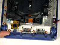
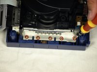
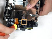
Drehe die Platine so, dass die grüne Platine dir zugewandt ist, wie in der ersten Abbildung gezeigt.
-
Drehe die Platine um, so dass sie wie in der zweiten Abbildung dargestellt ausgerichtet ist.
-
Drehe den kleinen Knopf mit einem Kreuzschlitzschraubendreher # 1 ganz leicht gegen den Uhrzeigersinn - ein paar Grad bis höchstens eine Vierteldrehung.
Isn't it supposed to be counter clockwise? I read somewhere that turning it clockwise weakens the laser.
Does anyone know the initial ohm potentiometer setting on Nintendo Gamecube DOL-001 (factory) on the pcb driver (RJB2281A-1 POT 0-900 OHM) THANK YOU
You don't. The author just duct taped a step to the end of the laser replacement guide and called it a day
-


Um das Gerät wieder zusammenzubauen, folge der Anleitung in ungekehrter Reihenfolge.
Um das Gerät wieder zusammenzubauen, folge der Anleitung in ungekehrter Reihenfolge.
Rückgängig: Ich habe diese Anleitung nicht absolviert.
29 weitere Personen haben diese Anleitung absolviert.
Besonderer Dank geht an diese Übersetzer:innen:
100%


Diese Übersetzer:innen helfen uns, die Welt zu reparieren! Wie kann ich mithelfen?
Hier starten ›
Team

Cal Poly, Team 6-2, Maness Fall 2009 Mitglied von Cal Poly, Team 6-2, Maness Fall 2009
CPSU-MANESS-F09S6G2
4 Mitglieder
45 Anleitungen geschrieben
6 Kommentare
I don't understand why you have steps 11-17. In step 10, you can clearly see the board with the screw that needs adjusting. Taking apart the rest of the GameCube is utterly unnecessary. After following the guide in full, I thought, 'Why did I just dismantle all that other stuff when I didn't even NEED to?'
Once the assembly is removed from the metal covering the board, it is a simple matter to turn the screw to increase the laser strength. I did this after my initial adjustment didn't work. I ignored steps 11-17 and everything works perfectly now. My old games which simply would not load, now do. Thanks for the advice leading up to step 10 though. That part was helpful.
I wouldn't say it's a quarter of a turn, a few degrees clockwise do the trick. I tried a quarter of a turn the first time and it made the disk unit useless as it didn't recognise any gamecube disk.
Thanks for the detailed pictures! I was able to get everything taken apart, and fixed the read error I was having after a couple of readjustments.
One important note: the lens screw should be turned counter-clockwise, not clockwise. A quarter turn is also likely to be too much; better to adjust a few degrees at a time and test repeatedly until the right setting is found.
gameFAQs.com has a lens calibration guide, with notes on how to reassemble the GameCube for testing without screwing everything back together.
I also agree that steps 11-17 can be skipped, as well as step 5 to remove the controller ports.
Steps 11+ are definitely not needed and 1/4 turn is more than 200ohms, way too much. It has to be moved by a hair (almost literally), the potentiometer is extremely sensitive. And I would personally recommend some form of multimeter, as to not go turning that screw blindly.
Great guide, this fixed my problem. Would like to be clarified if you need to follow steps 11-17 make the power adjustment.
Hell yes dude, thank you! The console I got from my grandma with SA2B as a preteen finally stopped reading discs completely yesterday after having trouble on and off for years, I was afraid I'd have to replace the entire drive assembly but adjusting the lens power worked!
Also, to complete step 6, the fan is a little tricky to remove, at least on a DOL-001 US console. You have to sort of rotate the fan assembly outward clockwise, by pulling the front of the fan out to the left a bit, so the plastic can clear the drive assembly.